Symmetry control circuit of a trailing edge phase control dimmer circuit

Active Publication Date: 2018-09-18
OZUNO HLDG LTD
View PDF10 Cites 0 Cited by
  • Summary
  • Abstract
  • Description
  • Claims
  • Application Information

AI Technical Summary

Benefits of technology

[0009]Accordingly, in one aspect, the present invention provides a symmetry control circuit for a trailing edge phase control dimmer circuit for controlling alternating current (AC) power to a load, the symmetry control circuit including: a bias signal generator circuit configured to monitor non-conduction periods of each half cycle of said AC power for an elapsed duration of the non-conduction periods, and generate a bias signal voltage based on the elapsed duration, whereby an amplitude of the bias signal voltage is proportional to the elapsed duration of the non-conduction periods; and a bias signal converter circuit configured to convert the bias signal voltage to a bias signal current, wherein the bias signal current is added to a reference current of a conduction period timing circuit configured to determine said conduction periods, and wherein the conduction period timing circuit is configured to alter one of the conduction periods immediately following one of the non-conduction periods based on the bias signal current when added to the reference current to compensate for a phase shift of a zero-crossing of said one of the non-conduction periods corresponding to an elapsed duration of said one of the non-conduction periods so as to restore symmetry of the non-conduction periods of each half cycle of AC power.
[0010]In another aspect, the present invention provides a method of controlling symmetry of non-conduction periods of each half cycle of alternating current (AC) power for a trailing edge phase control dimmer circuit for controlling said AC power to a load, the method including: monitoring non-conduction periods of each half cycle of said AC power for an elapsed duration of the non-conduction periods; generating a bias signal voltage based on the elapsed duration, whereby an amplitude of the bias signal voltage is proportional the elapsed duration of the non-conduction periods; converting the bias signal voltage to a bias signal current; adding the bias signal current to a reference current of a conduction period timing circuit configured to determine said conduction periods; and altering one of the conduction periods immediately following one of the non-conduction periods based on the bias signal current when added to the reference current to compensate for a phase shift of a zero-crossing of said one of the non-conduction periods corresponding to an elapsed duration of said one of the non-conduction periods so as to restore symmetry of the non-conduction periods of each half cycle of AC power.

Problems solved by technology

The ripple voltage in the load is ultimately the cause of phase-shift effects on the zero-crossing of the dimmer rectified voltage.

Method used


Image

  • Symmetry control circuit of a trailing edge phase control dimmer circuit
  • Symmetry control circuit of a trailing edge phase control dimmer circuit
  • Symmetry control circuit of a trailing edge phase control dimmer circuit

Examples


Embodiment Construction

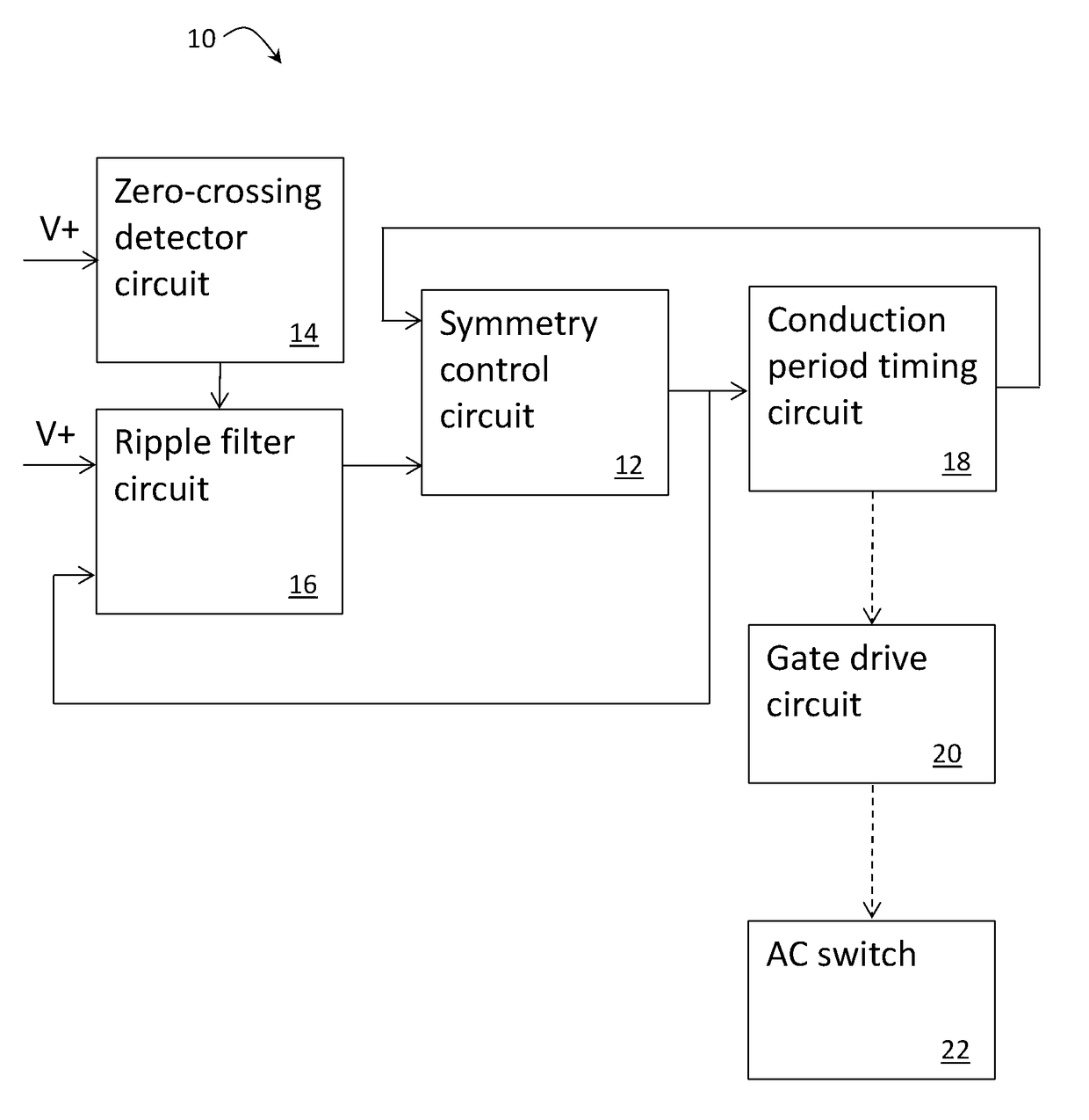
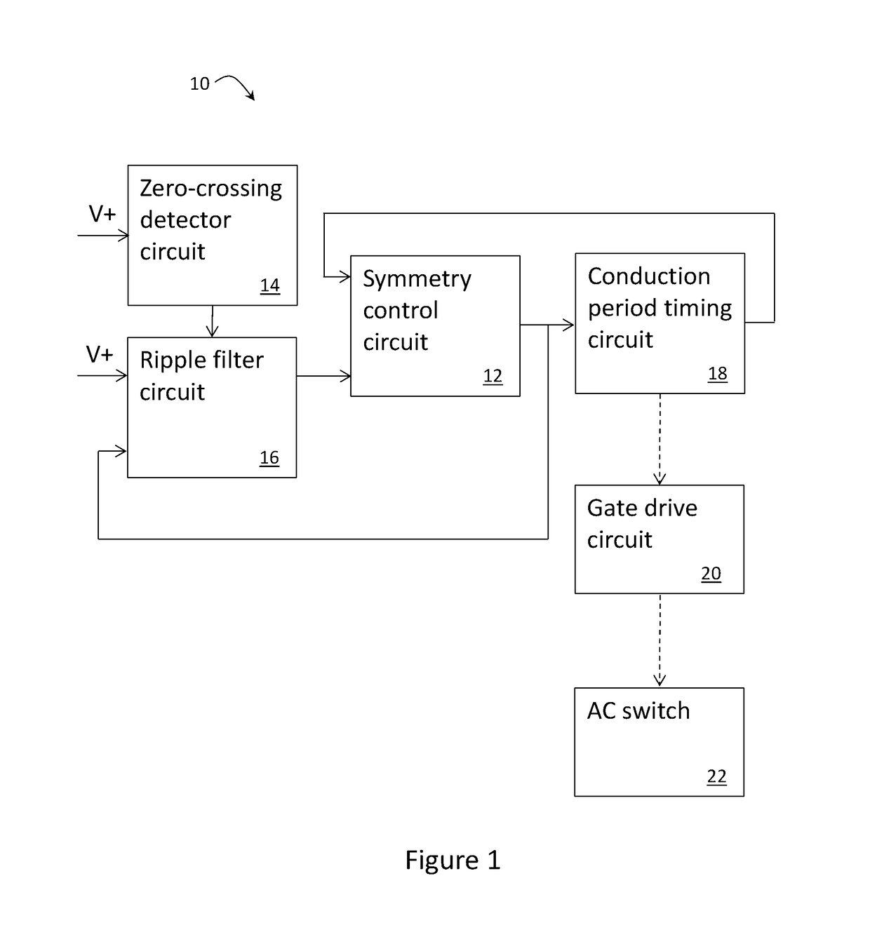
[0025]FIG. 1 shows some of the circuits of a 2-wire trailing edge dimmer circuit 10 according to an embodiment of the present invention that are configured to control power to a load. More specifically, FIG. 1 shows those circuits that are configured to operate in association with a symmetry control circuit 12. It will be appreciated by those persons skilled in the art that many of the circuits of the dimmer circuit 10 do not affect operation of the symmetry control circuit 12 and thus will not be discussed in detail herein.

[0026]The dimmer circuit 10 shown in FIG. 1 includes an AC switching circuit 22 connected to a gate drive circuit 20 for controlling switching ON and OFF of the switching circuit 22 to control AC power to the load. The above mentioned conduction period occurs when AC power is switched ON so as to be conducted to the load and the non-conduction period is when the AC power is switched OFF so as to not be conducted to the load. The switching circuit 22, for instance...


PUM


Abstract

A symmetry control circuit for a trailing edge phase control dimmer circuit for controlling alternating current (AC) power to a load, the symmetry control circuit including: a bias signal generator circuit configured to monitor non-conduction periods of each half cycle of said AC power for an elapsed duration of the non-conduction periods, and generate a bias signal voltage based on the elapsed duration, whereby an amplitude of the bias signal voltage is proportional to the elapsed duration of the non-conduction periods; and a bias signal converter circuit configured to convert the bias signal voltage to a bias signal current, wherein the bias signal current is added to a reference current of a conduction period timing circuit configured to determine said conduction periods, and wherein the conduction period timing circuit is configured to alter one of the conduction periods immediately following one of the non-conduction periods based on the bias signal current when added to the reference current to compensate for a phase shift of a zero-crossing of said one of the non-conduction periods corresponding to an elapsed duration of said one of the non-conduction periods so as to restore symmetry of the non-conduction periods of each half cycle of AC power.

Description

[0001]This application is a U.S. National Stage of International Application No. PCT / AU2015 / 000298, filed May 20, 2015, which claims benefit of Australia Application No. 2014901924, filed on May 22, 2014, which are incorporated by reference herein.TECHNICAL FIELD[0002]The present invention relates to a symmetry control circuit of a trailing edge phase control dimmer circuit for controlling alternating current (AC) power to a load, and a method of controlling symmetry of non-conduction periods of each half cycle of the alternating current (AC) power for the trailing edge phase control dimmer circuit.[0003]In particular, but not exclusively, the present invention relates to a symmetry control circuit for a 2-wire trailing edge phase control dimmer circuit for controlling a capacitive load, such as a driver for LED lights.BACKGROUND OF INVENTION[0004]Dimmer circuits are commonly used to control power, in particular alternating current (AC) mains power, to a load, such as a light source...

Claims


Application Information

Patent Timeline
Patent Type & Authority Patents(United States)
IPC IPC(8): H02M5/257H02M1/08H05B33/08H02M1/00H05B44/00
CPCH02M1/081H02M5/2573H05B39/08H05B33/0845G01R19/175H02M1/083H05B33/0809H05B41/3924H02M2007/4803H02M2001/0058H03K5/1536H05B39/044H05B45/10H02M7/4803Y02B70/10H02M1/0058
Inventor VANDERZON, JAMES
Owner OZUNO HLDG LTD
Why Eureka
Try Eureka