Pneumatically driven fluid dispenser

a fluid dispenser and pneumatic drive technology, applied in the direction of dispensers, liquid dispensers, holders, etc., can solve the problems of compromising the motor's performance, wasting, and inability to effectively perform the dispensing of other fluids using existing soap dispensing mechanisms

Active Publication Date: 2018-10-16
TOASTER LABS
View PDF117 Cites 3 Cited by
  • Summary
  • Abstract
  • Description
  • Claims
  • Application Information

AI Technical Summary

Problems solved by technology

However, the dispensing of other fluids may not effectively be performed using existing soap dispensing mechanisms inasmuch as residual fluid left in the dispenser may be messy, non-hygienic, or result in unacceptable waste.
However, environmental conditions such as moisture, dirt, and vibration may affect the flow of current through the coils, and compromise the motor's performance.
Motors may fail completely if too much current is supplied to the coils.
For instance, an electrical short between adjacent coils may reduce the resistance of the conductive path and significantly increase the current flowing through the coils.
The increased current may provide significant heat and result in damaged the coils, causing a motor “burn out.” Such motors often require complete replacement of at least the coils.
Such motors cannot provide translational motion of a continuous nature or for an arbitrary amount of translation.

Method used


Image

  • Pneumatically driven fluid dispenser
  • Pneumatically driven fluid dispenser
  • Pneumatically driven fluid dispenser

Examples


Embodiment Construction

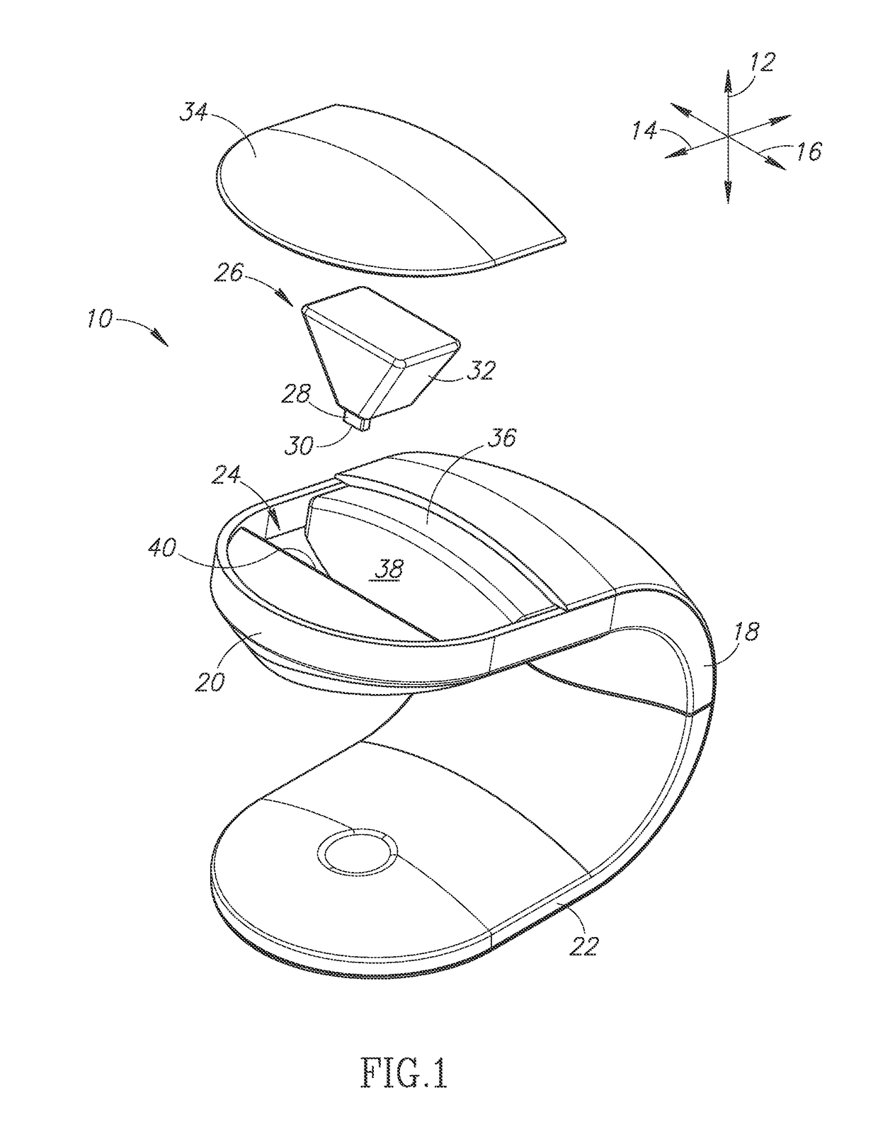
[0040]Referring to FIG. 1, a dispenser 10 may be understood with respect to a vertical direction 12, a longitudinal direction 14 perpendicular to the vertical direction 12, and a lateral direction 16 perpendicular to the vertical and longitudinal directions 12, 14. The vertical direction 12 may be perpendicular to a planar surface on which the dispenser 10 rests. Likewise, the lateral and longitudinal directions 14, 16 may be parallel to the support surface.

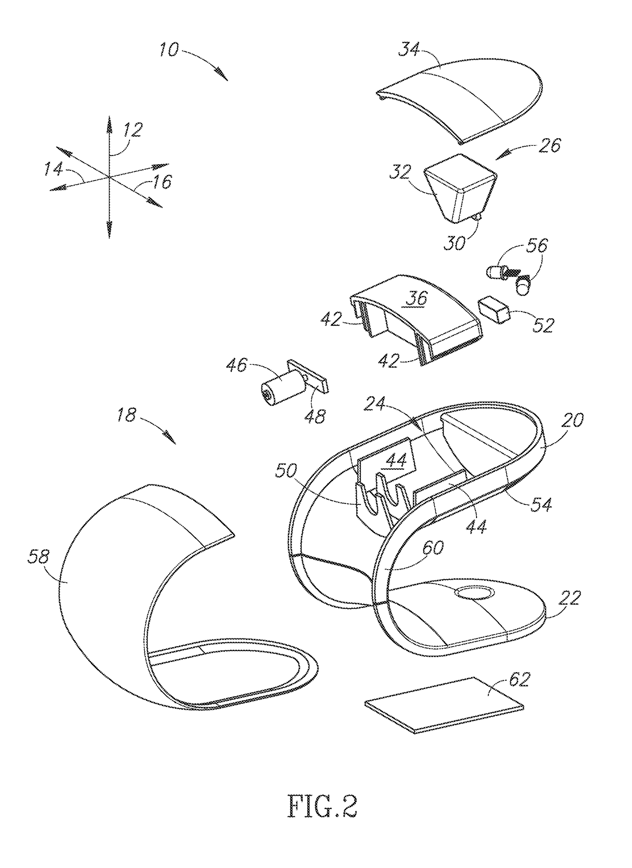
[0041]The dispenser 10 may include a housing 18 that has a C-shape in the longitudinal-vertical plane. Accordingly, the housing 18 may include an upper portion 20 and a base 22 such that a vertical gap is defined between the upper portion 20 and the base 22. The upper portion 20 may define a cavity 24 for receiving a reservoir 26. The reservoir 26 may include a neck 28 defining an opening 30 and a body 32 coupled to the neck 28. The neck 28 may be smaller such that the body 32 can be inserted into an opening through which the bod...


PUM


Abstract

A dispenser includes a housing, an aperture within the housing, a receptacle within the housing, and a pneumatically driven actuator. The receptacle removably receives a reservoir, such that when the reservoir is received by the receptacle, an outlet port of the reservoir is exposed through the aperture. When the pneumatically driven actuator is actuated, the pneumatically driven actuator provides a dispensing force that induces a flow of a predetermined volume of fluid within the reservoir through the exposed outlet port of the reservoir and dispenses the predetermined volume through the aperture. In some embodiments, the dispenser includes an internal pneumatic source. The internal pneumatic source may include an air compressor. The dispenser may include a pneumatic input port that receives a pneumatic hose. The dispensing force translates a piston in the reservoir a predetermined distance. The predetermined distance may be linearly proportional to the predetermined volume of dispensed fluid.

Description

PRIORITY CLAIM[0001]This patent application is a Continuation-in-Part of U.S. application Ser. No. 14 / 137,130, entitled AUTOMATIC FLUID DISPENSER, filed on Dec. 20, 2013, the contents of which are hereby incorporated by reference.BACKGROUND OF THE INVENTION[0002]Soap dispensers that are motion activated are well known. Such dispensers advantageously reduce the spread of germs and disease by not requiring any contact with the dispensers. Automated soap dispensers typically have large amounts of fluid that flows freely. The mechanisms of such dispensers retain a residual amount of soap, which is acceptable given the large reservoir size. Soap is left in the container. Soap also typically contacts the dispensing mechanism outside the container.[0003]Motion activated dispensing could be advantageously used for other fluids such as personal lubricants or other substances dispensed in medical applications. In particular, the lack of contamination may be ideal. However, the dispensing of o...

Claims


Application Information

Patent Timeline
Patent Type & Authority Patents(United States)
IPC IPC(8): B65D83/16B05B12/12A47K5/12A47K5/122B05B9/08B05B9/00
CPCA47K5/1211A47K5/122B05B12/122B05B9/002B05B9/0838A47K5/1217
Inventor BUCKALTER, AMY CAROLHADLEY, JONATHAN B.DIENER, ALEXANDER M.WILL, KRISTIN M.COHEN, GORDON
Owner TOASTER LABS
Why Eureka
Try Eureka