Check patentability & draft patents in minutes with Patsnap Eureka AI!

Active vibration control actuator

a technology of active vibration control and actuator, which is applied in the direction of rotorcraft, aircrafts, vehicles, etc., can solve the problems of negating the desired weight reduction, and affecting the flight speed of the aircra

Active Publication Date: 2018-10-16
SIKORSKY AIRCRAFT CORP
View PDF38 Cites 3 Cited by
  • Summary
  • Abstract
  • Description
  • Claims
  • Application Information

AI Technical Summary

Benefits of technology

Effectively suppresses airframe vibrations across multiple frequencies, reducing weight and complexity while maintaining effectiveness, even in vehicles without mounting struts, by utilizing centrifugal forces and adjustable inertial loads.

Problems solved by technology

Forces and moments are transmitted through the gearbox into the airframe, resulting in airframe vibration.
Although effective, this approach is inadequate in certain situations, such as a vehicle having a gearbox secured directly to the airframe, without mounting struts.
This method is heavy as it requires multiple eccentric masses powered by multiple motors and often these must be enclosed in separate housings to allow for geometric alignments that minimize unwanted moments and are thus not amenable to weight reductions.
However, since the system is circular in configuration, weight of housing components increases with radius squared, this negating the desired weight reduction.
Additionally aircraft sometimes experience multiple frequencies of ambient vibration caused by forward flight load on the rotor systems.
This is undesirable as it requires multiple such anti-vibration actuators to suppress multiple frequencies of ambient vibration.

Method used


Image

  • Active vibration control actuator
  • Active vibration control actuator
  • Active vibration control actuator

Examples


Embodiment Construction

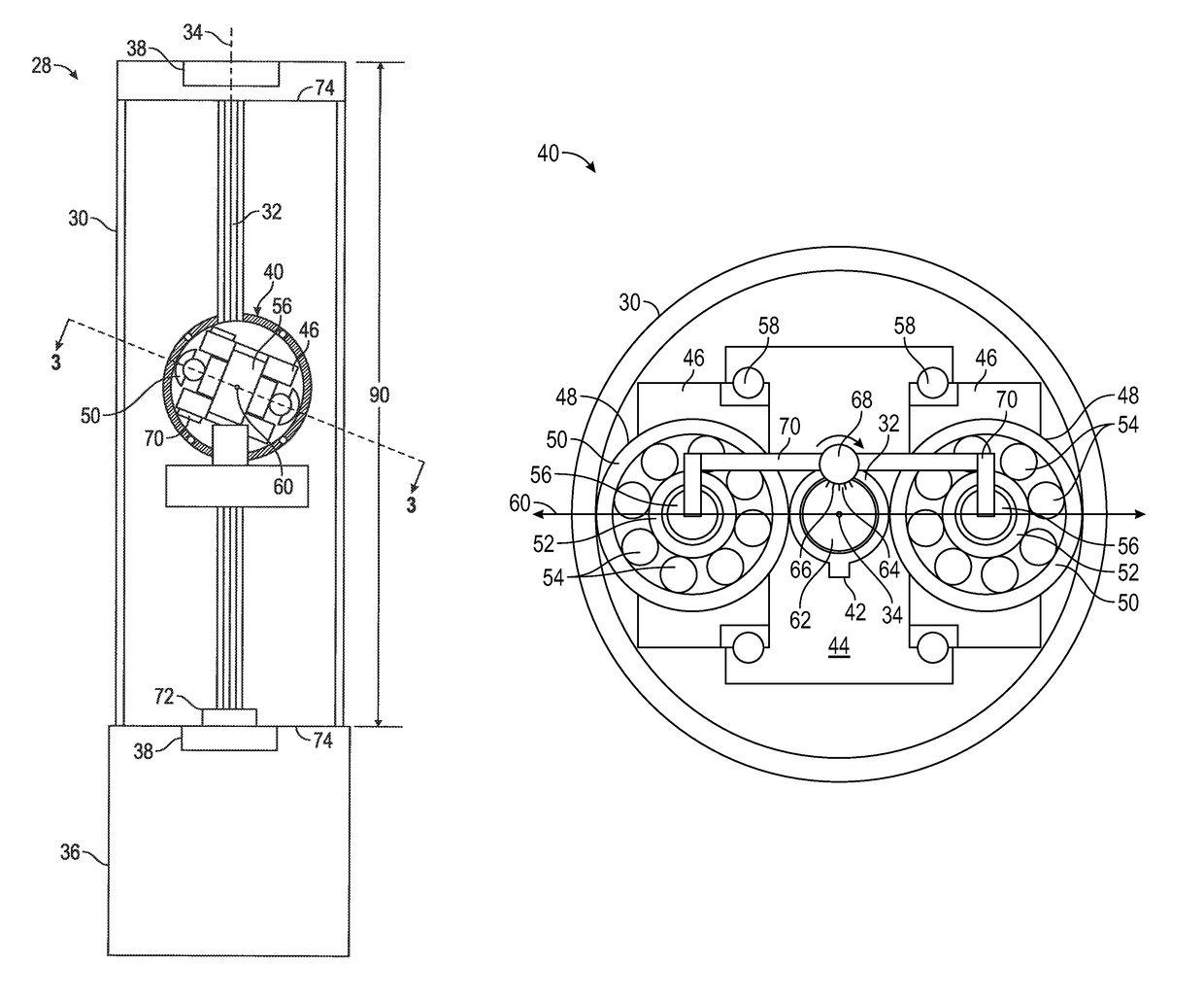
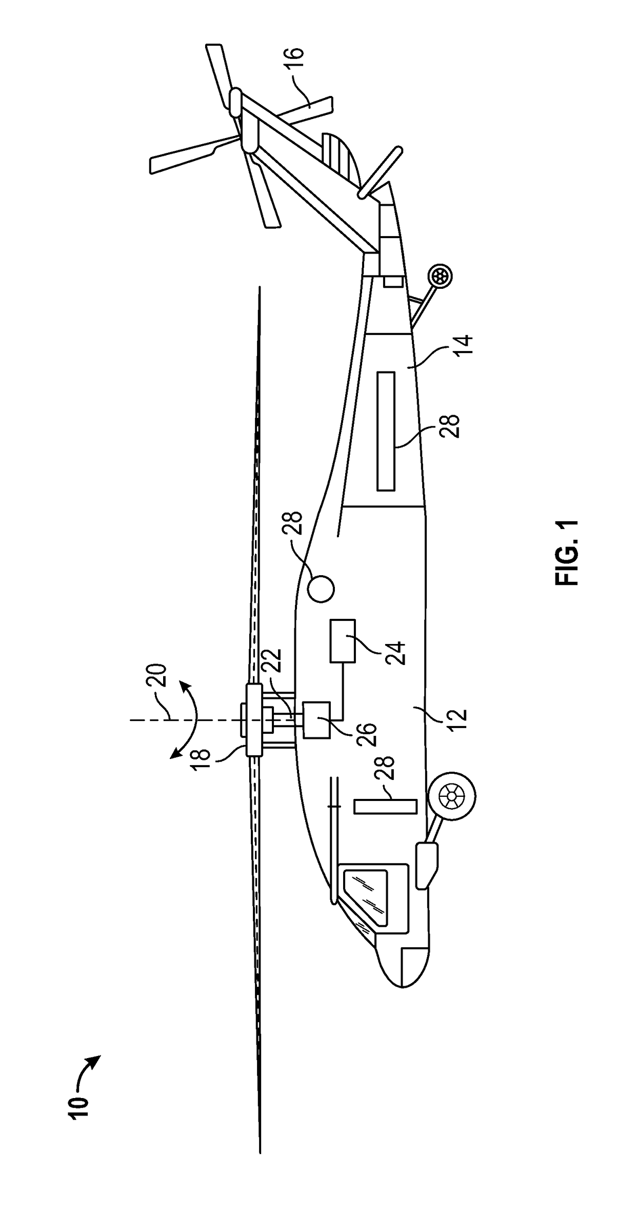
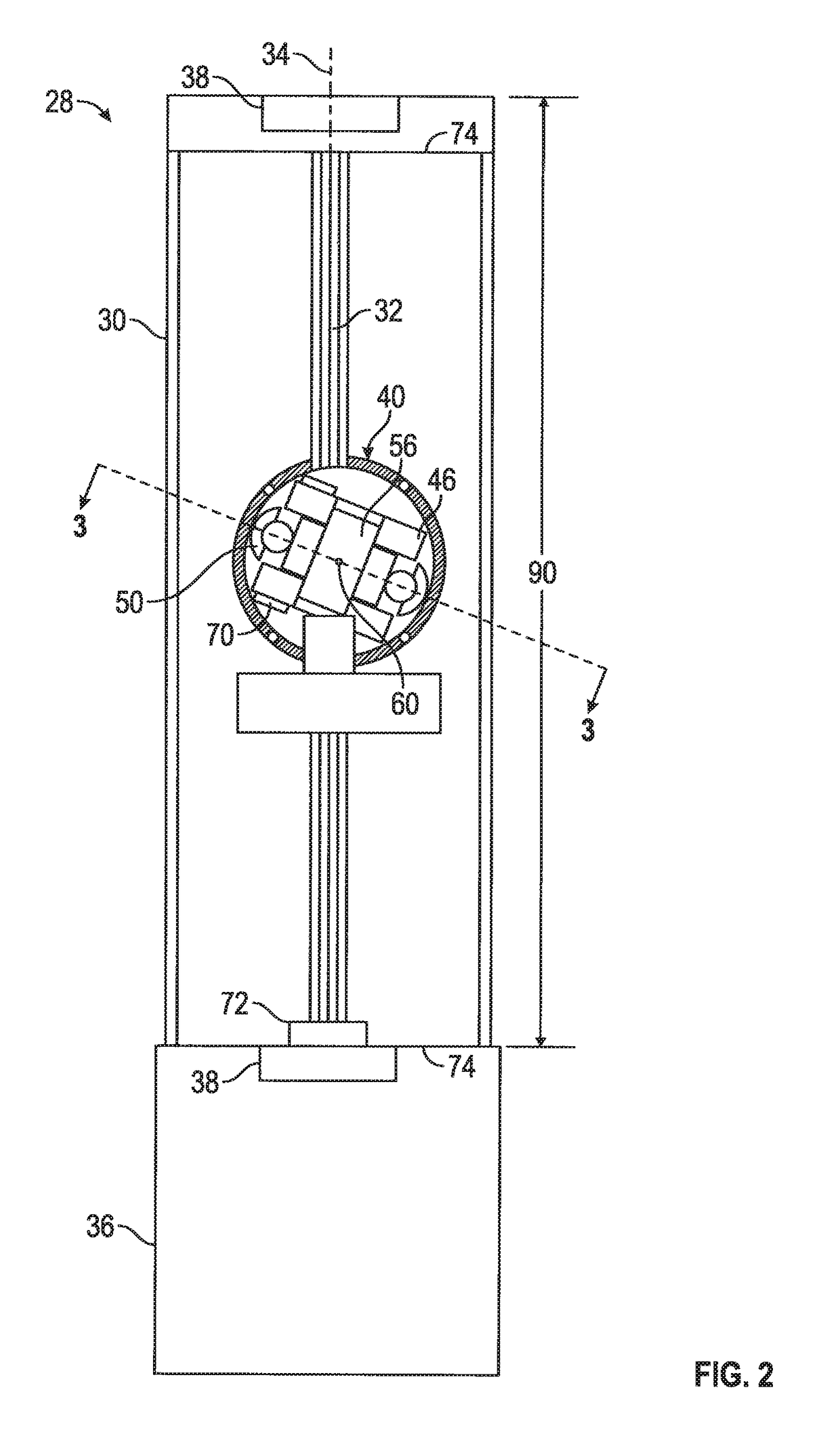
[0017]Shown in FIG. 1 is schematic view of an embodiment of an aircraft, in this embodiment a helicopter 10. The helicopter 10 includes an airframe 12 with an extending tail 14 and a tail rotor 16 located thereat. While the embodiment of a helicopter 10 described herein includes an extending tail 14 and tail rotor 16, it is to be appreciated that the disclosure herein may be applied to other types of rotor craft as well as helicopters 10 of other configurations. A main rotor assembly 18 is located at the airframe 12 and rotates about a main rotor axis 20. The main rotor assembly 18 is driven by a drive shaft 22 connected to a power source, for example, an engine 24 by a gearbox 26. To suppress vibration of the airframe 12 resulting from, for example, rotation of the main rotor assembly 18 about the main rotor axis 20, a number of active vibration control (AVC) actuators 28 are located in the airframe 12. In some embodiments, 3-6 AVC actuators 28 are utilized, although the number is ...


PUM


Abstract

A vibration control actuator includes a housing having a length between ends and a rotatable shaft located in the housing and extending along a housing length and which rotates about a shaft axis substantially parallel to the length. An inertia wheel assembly is operably connected to the rotatable shaft and configured to rotate therewith about the shaft axis. The inertia wheel assembly is in frictional contact with an inner wall of the housing and translatable to travel within the housing between the ends along at least a portion of the shaft axis.

Description

BACKGROUND[0001]The subject matter disclosed herein relates to the art of rotary wing aircraft and, more specifically to active vibration control or suppression in a rotary wing aircraft.[0002]Rotary wing aircraft, or rotorcraft, can generate significant vibratory responses during operation. The primary source of such vibration is that generated by the main rotor system rotating at the blade passing frequency. Forces and moments are transmitted through the gearbox into the airframe, resulting in airframe vibration. One approach to counteracting such vibration involves replacing a rigid gearbox mounting strut with a compliant strut and parallel hydraulic actuator. A control computer commands the actuator such that the gearbox is selectively vibrated to produce inertial forces which minimize airframe vibrations. Although effective, this approach is inadequate in certain situations, such as a vehicle having a gearbox secured directly to the airframe, without mounting struts.[0003]Anoth...

Claims


Application Information

Patent Timeline
Patent Type & Authority Patents(United States)
IPC IPC(8): B64C27/00
CPCB64C27/001B64C2027/004
Inventor WELCH, WILLIAM A.
Owner SIKORSKY AIRCRAFT CORP
Features
  • R&D
  • Intellectual Property
  • Life Sciences
  • Materials
  • Tech Scout
  • Unparalleled Data Quality
  • Higher Quality Content
  • 60% Fewer Hallucinations
Learn More