Surgical instrument with a manual control

a control device and surgical instrument technology, applied in the field of surgical instruments with manual control devices, can solve the problems of not being able to make adequate allowance for the actual movement of the hand, and the thumb and finger of the hand cannot mov

Active Publication Date: 2018-10-23
KARL STORZ GMBH & CO KG
View PDF14 Cites 0 Cited by
  • Summary
  • Abstract
  • Description
  • Claims
  • Application Information

AI Technical Summary

Benefits of technology

[0008]It is an object of the present disclosure to provide an improved surgical instrument with a manual control device for actuation by hand that makes convenient and ergonomic actuation possible, in particular by opening and closing the hand.

Problems solved by technology

Within the context of the improvement to be achieved, it has been found that a problem with known manual control devices is that they do not sufficiently make allowance for the actual movement of the hand of a user during the opening and closing of the hand.
This has the effect that known manual control devices may appear to be ergonomically and conveniently operable when the proposed technique is considered, but in practice are not found to be so by the user, especially in the case of lengthy procedures.
It has also been found in this connection that at least part of the problem appears to be that the thumb and fingers of a hand do not move precisely on a circular path during opening as in the case of a hinge.

Method used


Image

  • Surgical instrument with a manual control
  • Surgical instrument with a manual control
  • Surgical instrument with a manual control

Examples


first embodiment

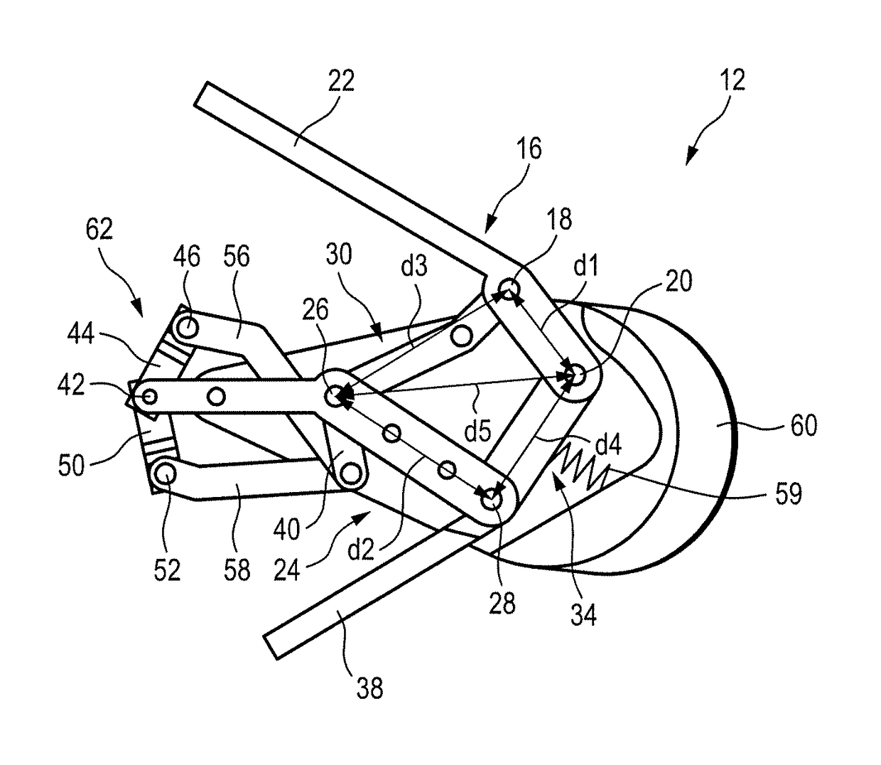
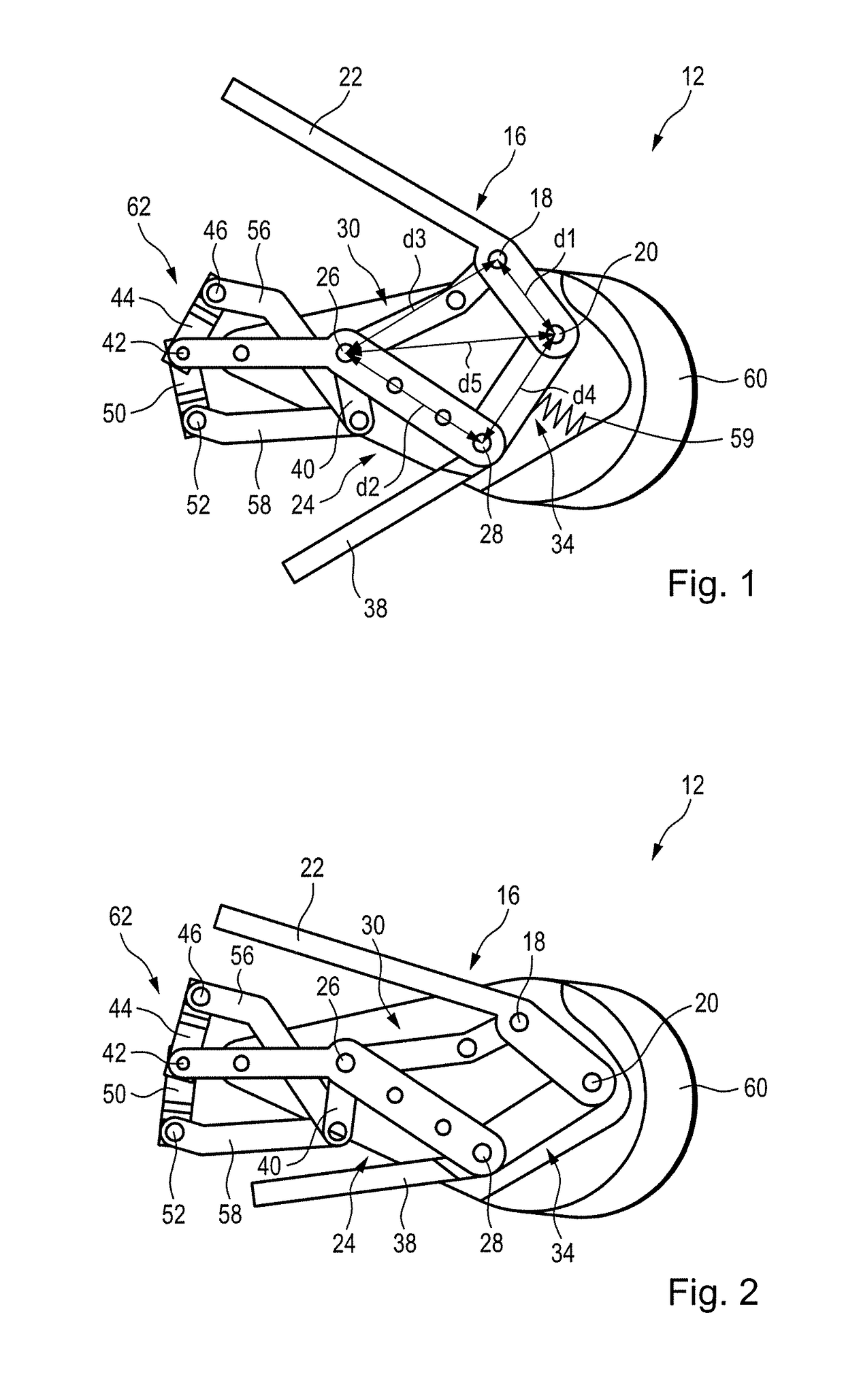
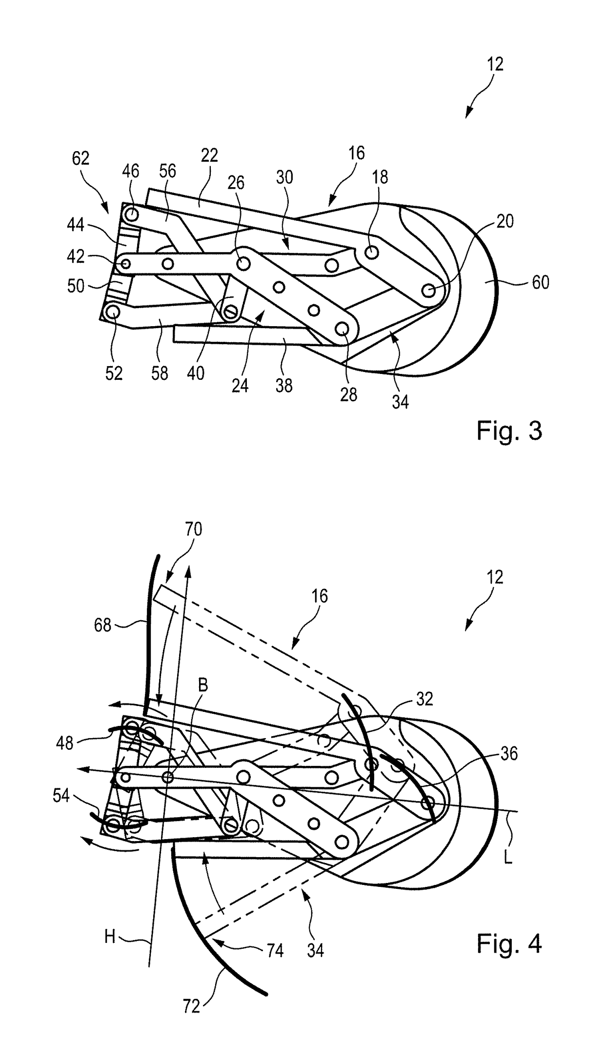
[0095]FIG. 3 finally shows the first embodiment according to FIG. 1 in a closed state.

[0096]FIG. 4 shows the representation according to FIG. 3 with a solid line and the representation according to FIG. 1 with a double dashed line in a superposed form. This representation allows a good appreciation of the movements of the individual parts. The previously explained paths of movement are also depicted.

[0097]Also shown here as an orientation aid are a longitudinal direction L of the control device 12 and a vertical direction H running perpendicularly thereto. A direction that runs both perpendicularly to the longitudinal direction L and perpendicularly to the vertical direction H is depicted as the width direction B and here is perpendicular to the plane of the drawing.

[0098]Additionally depicted is a finger movement path 68, which describes the movement of the first distal end 70 of the finger lever 16. Also depicted is a thumb movement path 72, which describes the movement of a secon...

second embodiment

[0102]FIG. 8 shows the surgical instrument with a working portion 91, which here is actuated on the basis of control signals of the haptic input device 66.

[0103]It can be seen here that the width of the control device 12, that is to say the extent along the width direction B, is at least 50% of the width of a human hand, or at least 75%, or at least 85% or at least 95%.

[0104]FIG. 9 shows the representation according to FIG. 7 in a first side view. FIG. 10 shows the representation according to FIG. 7 in a second side view. A second measuring device 92 can be seen here, designed for determining a degree of opening of the control device 12, for an exemplary embodiment, an opening angle of the control device. For this, the measuring device 92 has a sensor 94 and a signal transmitter 96, which here is coupled to the thumb lever 34, for an exemplary embodiment, by way of a gear mechanism.

[0105]In the case of other designs, the signal transmitter 96 may also be coupled to the connecting le...

third embodiment

[0106]FIG. 11 shows the control device 12 with a placed-on hand 14.

[0107]FIG. 12 shows the first embodiment of the control device 12 with a placed-on hand 14.


PUM


Abstract

Surgical instrument with a manual control device for actuation with a hand, wherein the control device can be displaced between a closed position and an opened position and the control device has: a finger lever with a first point of articulation and a second point of articulation, a central element with a third point of articulation and a fourth point of articulation, a connecting lever, which is pivotably arranged at the first point of articulation and at the third point of articulation, and a thumb lever, which is pivotably arranged at the second point of articulation and at the fourth point of articulation.

Description

CROSS REFERENCES TO RELATED APPLICATIONS[0001]This application claims priority from German patent application 10 2014 115 600.5, filed on Oct. 27, 2014. The entire contents of these priority applications are incorporated herein by reference.BACKGROUND OF THE INVENTION[0002]The present disclosure relates to a surgical instrument with a manual control device for actuation by hand, wherein the control device can be displaced between a closed position and an opened position. The displacement takes place by a manual action being imparted to the control device by the hand of a user, in that the latter opens and closes the hand.[0003]There are many tools and instruments that a user actuates manually with his or her hand. Some of these instruments require special ergonomics for the actuation, for example because the actuation of the instrument must be possible with a fine touch, because frequently repeated actuation of the instrument is required or because certain actuating positions of the...

Claims


Application Information

Patent Timeline
Patent Type & Authority Patents(United States)
IPC IPC(8): A61B17/00A61B17/29A61B34/00
CPCA61B17/00234A61B17/2909A61B34/70A61B34/74A61B34/76A61B2017/2919A61B2017/0046A61B2017/00398A61B2017/00424A61B2017/00477
Inventor ABRI, OMIDSCHRADER, STEPHANFORSTER, JONAS
Owner KARL STORZ GMBH & CO KG
Why Eureka
Try Eureka