Charge steering high density electrode array

a high density electrode array and charge steering technology, applied in the field of deep brain stimulation, can solve the problems of electrode displacement or dislocation, incorrect placement and calibration of the stimulator, and the potential serious side effects of dbs, and achieve the effect of minimizing the adverse side effects of the electric field

Active Publication Date: 2018-11-13
UNIV OF UTAH RES FOUND
View PDF35 Cites 5 Cited by
  • Summary
  • Abstract
  • Description
  • Claims
  • Application Information

AI Technical Summary

Benefits of technology

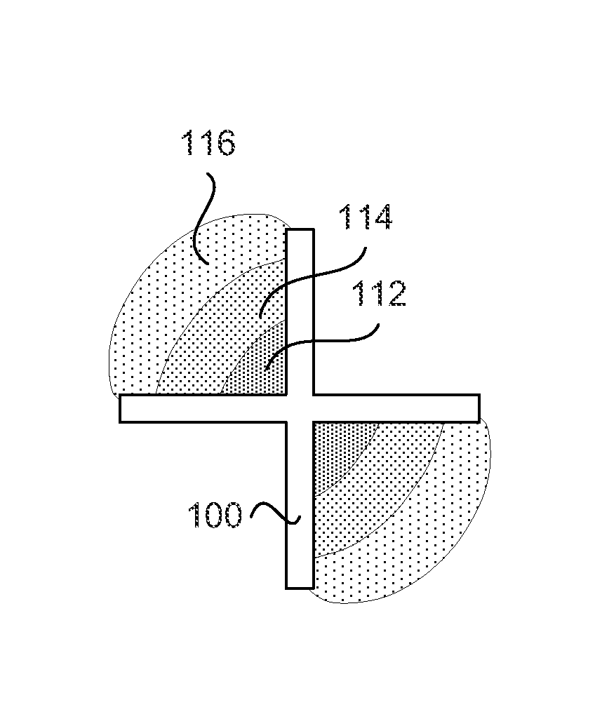
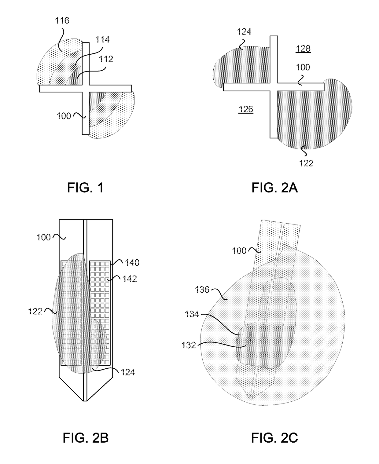
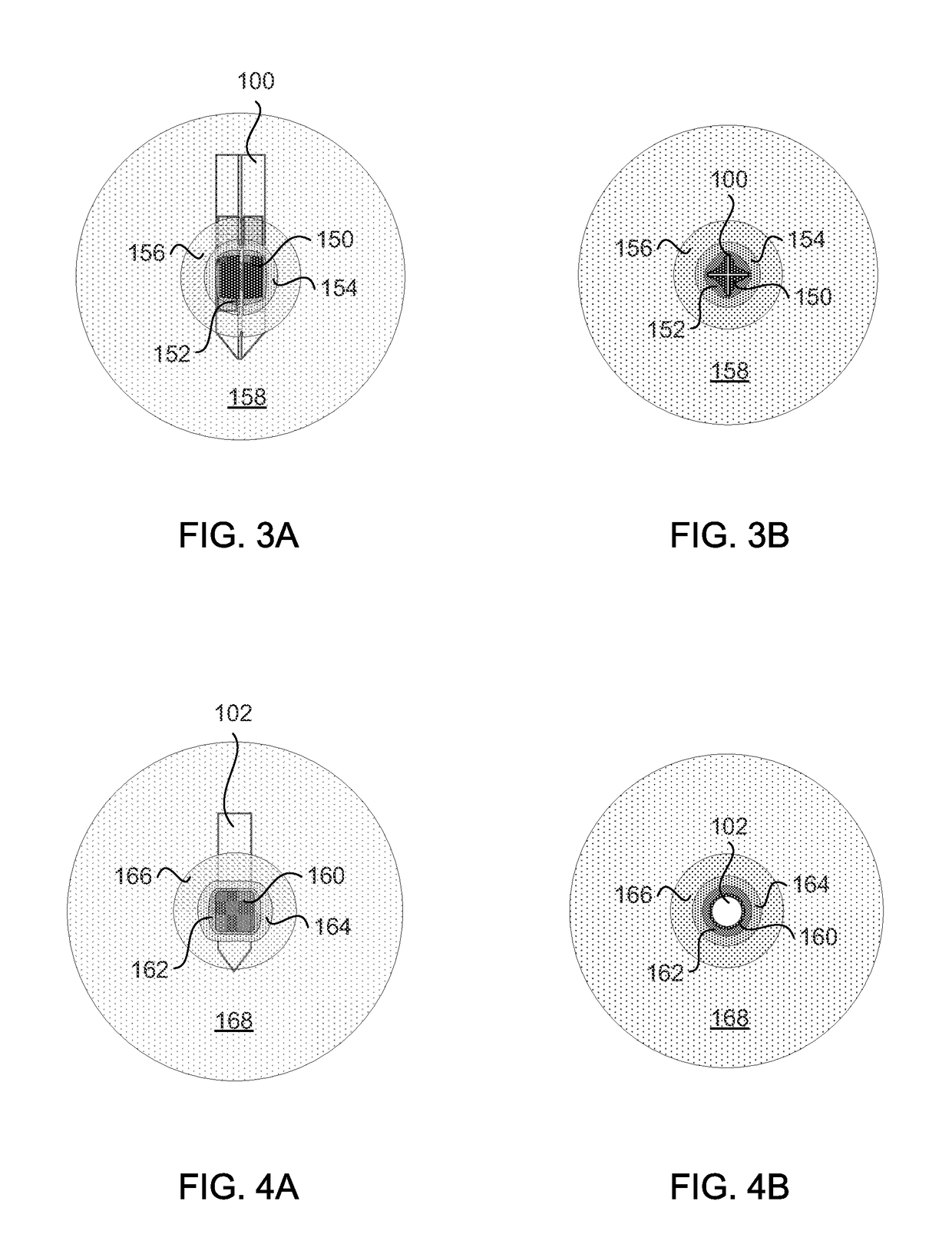
[0011]In a configuration, the operation of delivering an electric field from the stimulating electrode that substantially matches the three dimensional volume of the region of neural tissue can further include: delivering an electric field from the stimulating electrode that estimates the three dimensional boundaries of the region of neural tissue; measuring the electric field from the stimulating electrode relative to the region of neural tissue; and adjusting the electric field of the stimulating electrode to substantially spatially match the three dimensional boundaries of the region of neural tissue. In another configuration, the operation of delivering an electric field from the stimulating electrode that substantially matches the three dimensional boundaries of the region of neural tissue can further include: delivering an electric field from the stimulating electrode that estimates the three dimensional volume of the region of neural tissue; evaluating the effect of the electric field from the stimulating electrode; and adjusting the electric field of the stimulating electrode based on the effect to minimize an adverse side effect of the electric field.

Problems solved by technology

While DBS can be helpful for some patients, DBS also has the potential for serious side effects.
Such side effects may be related to the incorrect placement and calibration of the stimulator.
Because the brain can shift slightly during surgery, there is the possibility that the electrodes can become displaced or dislodged.
The misplacement of the lead (e.g., electrode) may cause more profound complications such as personality changes, potentially requiring electrode repositioning.

Method used


Image

  • Charge steering high density electrode array
  • Charge steering high density electrode array
  • Charge steering high density electrode array

Examples


Embodiment Construction

[0035]Before the present invention is disclosed and described, it is to be understood that this invention is not limited to the particular structures, process steps, or materials disclosed herein, but is extended to equivalents thereof as would be recognized by those ordinarily skilled in the relevant arts. It should also be understood that terminology employed herein is used for the purpose of describing particular embodiments only and is not intended to be limiting. The same reference numerals in different drawings represent the same element.

[0036]It must be noted that, as used in this specification and the appended claims, the singular forms “a,”“an,” and “the” include plural referents unless the context clearly dictates otherwise. Thus, for example, reference to “an electrode” includes one or more of such electrodes, reference to “the conductor” includes reference to one or more of such conductors, and reference to “stimulating” includes one or more of such steps.

[0037]In descri...


PUM


Abstract

Technology for deep brain stimulating including devices, systems, computer circuitry, and associated methods is provided. A deep brain stimulating device (100) can include a semiconductor substrate, an array of electrodes (140) coupled to the semiconductor substrate, and circuitry operable to control the array of electrodes (140). Each electrode (142) can be operable to function as an anode, a cathode, a common, or a float independent of other electrodes in the array to create highly configurable electric fields (122, 124).

Description

RELATED APPLICATIONS[0001]This application claims the benefit of and hereby incorporates by reference U.S. Provisional Patent Application Ser. No. 61 / 647,780, filed May 16, 2012.GOVERNMENT INTEREST[0002]This invention was made with government support under K25 NS053544 awarded by the National Institutes of Health. The government has certain rights in the invention.FIELD OF THE INVENTION[0003]The present invention relates generally to technology for deep brain stimulation (DBS). Accordingly, the present invention involves using an array of electrodes which can be implanted in the brain to provide controllable electrical fields for DBS.BACKGROUND OF THE INVENTION[0004]Deep brain stimulation (DBS) is a surgical treatment involving the implantation of a medical device that sends electrical current pulses to specific regions of the brain. DBS in select brain regions has provided various therapeutic benefits for otherwise treatment-resistant movement and affective disorders such as chroni...

Claims


Application Information

Patent Timeline
Patent Type & Authority Patents(United States)
IPC IPC(8): A61N1/05A61N1/36
CPCA61N1/0534A61N1/36139A61N1/36185A61N1/36182A61N1/3615
Inventor DORVALL, II, ALAN DALEWILLSIE, ANDREW COLIN
Owner UNIV OF UTAH RES FOUND
Why Eureka
Try Eureka