Black hole boundary conditions

a boundary condition and black hole technology, applied in the field of modeling methods, can solve the problems of imperfect models and images, difficult to accurately represent the earth structure completely, and corrupt images, so as to prevent any distortion of the resulting image data

Active Publication Date: 2018-11-13
CONOCOPHILLIPS CO
View PDF36 Cites 0 Cited by
  • Summary
  • Abstract
  • Description
  • Claims
  • Application Information

AI Technical Summary

Benefits of technology

[0013]The present disclosure is therefore a new modeling method where the boundary condition is configured as a “black hole,” where no energy can propagate through the boundary to corrupt the subsequent imaging process. In other words, the energy that enters the black hole space is eliminated and is not allowed to corrupt the rest of modeling images. By applying this new condition selectively to various parts of the model or the processing of real data, the data can then be completely processed and the image compared with or without the black hole boundary conditions. This allows the modeler or processor to understand the impact of the black hole region on the final image and understand the region or regions of the model that are likely incorrectly described and modeled.
[0022]The black hole boundary conditions exist so that during modeling and processing stage, any energy waves entering the region, exiting the region, or reflecting off the region will be mathematically eliminated so as to prevent any distortion to the resulting image data.

Problems solved by technology

When constructing models of geological structures in the computer, it is difficult to precisely and accurately represent the earth structure completely.
Thus errors in the construction lead to imperfect models and images of the resulting seismic data.
Unless the modeling or processing is perfect, energy would otherwise propagate through the black hole region and perturb the good imaging outside the black hole, corrupting the image and leading to incorrect conclusions on the validity and accuracy of the model.

Method used


Image

  • Black hole boundary conditions
  • Black hole boundary conditions
  • Black hole boundary conditions

Examples


Embodiment Construction

[0034]In the following description numerous details are set forth to provide an understanding of the present disclosure. However, it will be understood by those of ordinary skill in the art that the present disclosure may be practiced without these details and that numerous variations or modifications from the described embodiments may be possible.

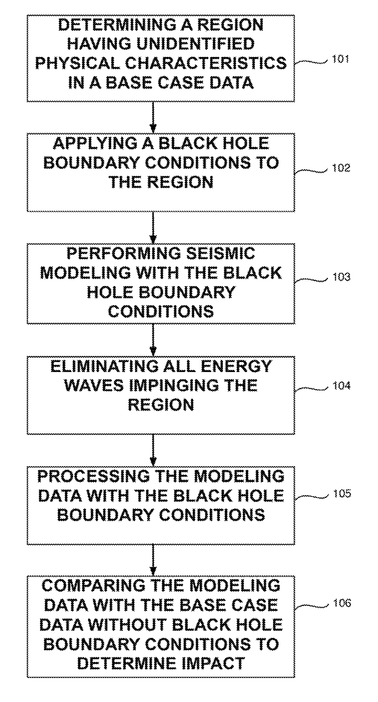
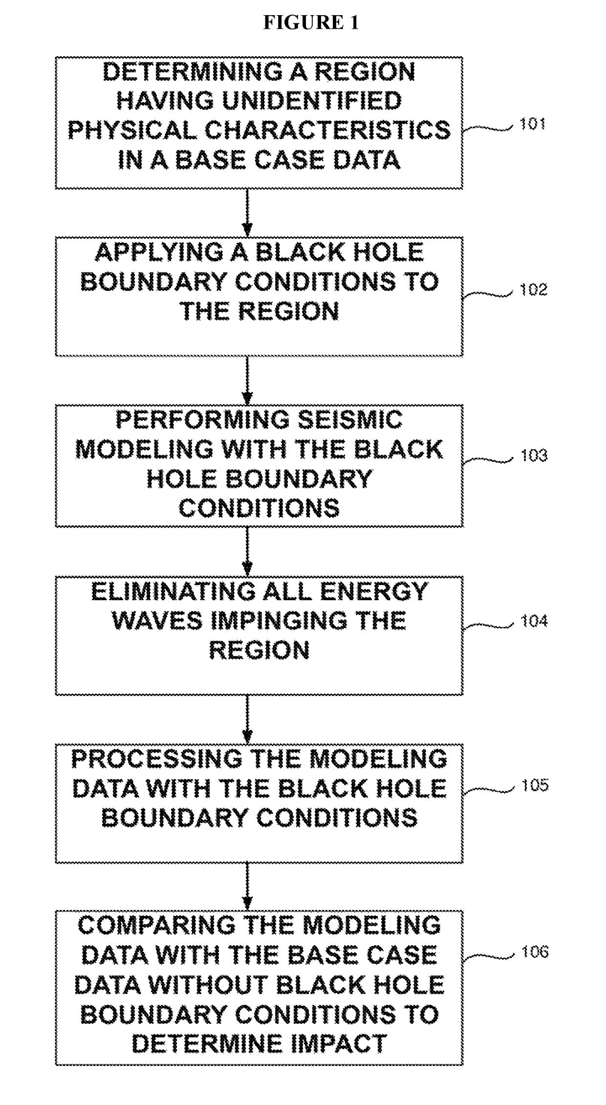
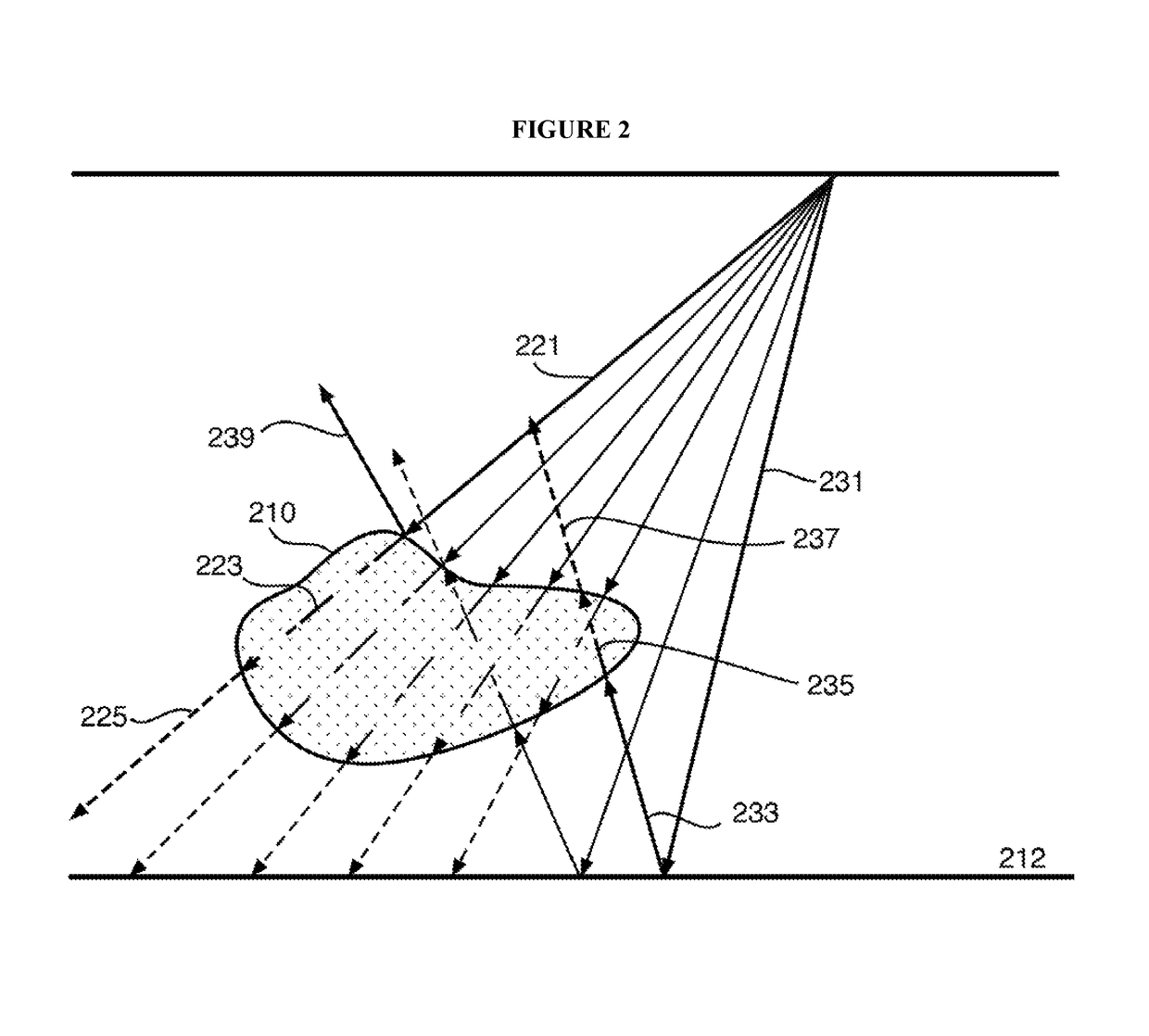
[0035]In the present disclosure, the concept is to create a black hole boundary / space around a black hole region in the model where accurate profile or velocity field data is not available or the area is suspected as causing distortion and corruption of the rest of the image. As such in both the modeling and processing steps, no energy is allowed to pass through the boundary or black hole space, hence no reflected or refracted energy from this region will be allowed to distort the remainder of the image.

[0036]FIG. 1 is a flow chart describing the steps of the modeling method described herein. The method is based on existing seismic data of...


PUM


Abstract

A method for modeling and analyzing the impact of different seismic surveying and imaging techniques on a subterranean formation uses a black hole boundary condition around a particular region in the formation where at least one of the physical characteristics is unclear and may distort the seismic modeling results. The black hole boundary conditions will eliminate any energy wave that enters, exit or reflect off the region so as to avoid any image distortion caused by this region. The resulted image data is compared with the image data obtained without using the black hole boundary conditions to determine the impact of this region, and proper correction can be made to more precisely and accurately model the formation.

Description

PRIOR RELATED APPLICATIONS[0001]This application is a non-provisional application which claims benefit under 35 USC § 119(e) to U.S. Provisional Application Ser. No. 62 / 117,511 filed Feb. 18, 2015, entitled “BLACK HOLE BOUNDARY CONDITIONS,” which is incorporated herein in its entirety.FIELD OF THE DISCLOSURE[0002]The disclosure generally relates to a modeling method to more accurately process the seismic data around an area of uncertain shape, size and other properties, and more particularly, to a modeling method that applies black hole boundary conditions such that the source of inaccurate estimation can be eliminated.BACKGROUND OF THE DISCLOSURE[0003]Seismic data is collected and processed in the oil industry as a means of imaging a potential geological target for subsequent drilling. Sophisticated computers and modeling software now allow for the careful pre-survey testing of actual field acquisitions scenarios prior to actually sending a crew out to collect a new dataset. Carefu...

Claims


Application Information

Patent Timeline
Patent Type & Authority Patents(United States)
IPC IPC(8): G06K9/00G01V1/28G01V1/36
CPCG01V1/36G01V1/282G01V2210/67G01V2210/32
Inventor EICK, PETER M.BREWER, JOEL
Owner CONOCOPHILLIPS CO
Why Eureka
Try Eureka