
Self locking safety spring clip

a safety spring and self-locking technology, applied in the direction of fastening means, taming and training devices, animal husbandry, etc., can solve the problems of owner being subjected to unexpected and uncontrollable consequences, difficult to release the spring clip, and difficult coupling and release of the traditional spring clip

Active Publication Date: 2018-11-27
FERPLAST
View PDF13 Cites 2 Cited by
  • Summary
  • Abstract
  • Description
  • Claims
  • Application Information

AI Technical Summary

Benefits of technology

[0018]The aim of this invention is to provide a safety spring clip of the self locking type which is able eliminate or significantly reduce the above-mentioned drawbacks.
[0019]The aim of this invention is also to provides a self locking spring clip which is simple to produce and, at the same time, of high quality, thus obtaining a finished product of significant interest for the customer.

Problems solved by technology

A first drawback is due to a certain difficulty in the step of coupling the spring clip to the retaining element, since a certain pressure must be exerted to open the closing device whilst trying to attach the spring clip to the gripping ring or other retaining element.
A further drawback is represented by the fact that the releasing of the spring clip is often difficult especially as a result of the fact that the animal, feeling that it is restrained, tends to make sudden movements which hinder the action by the owner.
In other contexts, such as the sports, nautical and mountaineering sectors, in which a certain speed of action is required, especially in emergency situations, the coupling and release of the traditional spring clips can be very difficult and in some cases become even dangerous due to unforeseeable consequences resulting from a lack of speed and precision during the coupling and / or releasing steps.
These situations constitute risks for the user who in the case of a leash may be subjected to strong tugs if the animal is large, whilst in other cases the owner may be subjected to unexpected and uncontrollable consequences.
Another drawback found by the operators in the “pet comfort” sector is represented by the fact that during the coupling of the traditional spring clip to the collar of the animal it is necessary to manually open the closing pin of the hook with inevitable retaining of the pet's collar.
Also in this case it is not easy to control since the animal tends to move both when it is freed and when it is about to be attached to the leash.

Method used


Image

  • Self locking safety spring clip
  • Self locking safety spring clip
  • Self locking safety spring clip

Examples


Embodiment Construction

[0018]The aim of this invention is to provide a safety spring clip of the self locking type which is able eliminate or significantly reduce the above-mentioned drawbacks.

[0019]The aim of this invention is also to provides a self locking spring clip which is simple to produce and, at the same time, of high quality, thus obtaining a finished product of significant interest for the customer.

[0020]This is achieved by means of a self locking spring clip whose features are described in the main claim.

[0021]The dependent claims of the solution according to this invention describe advantageous embodiments of the invention.

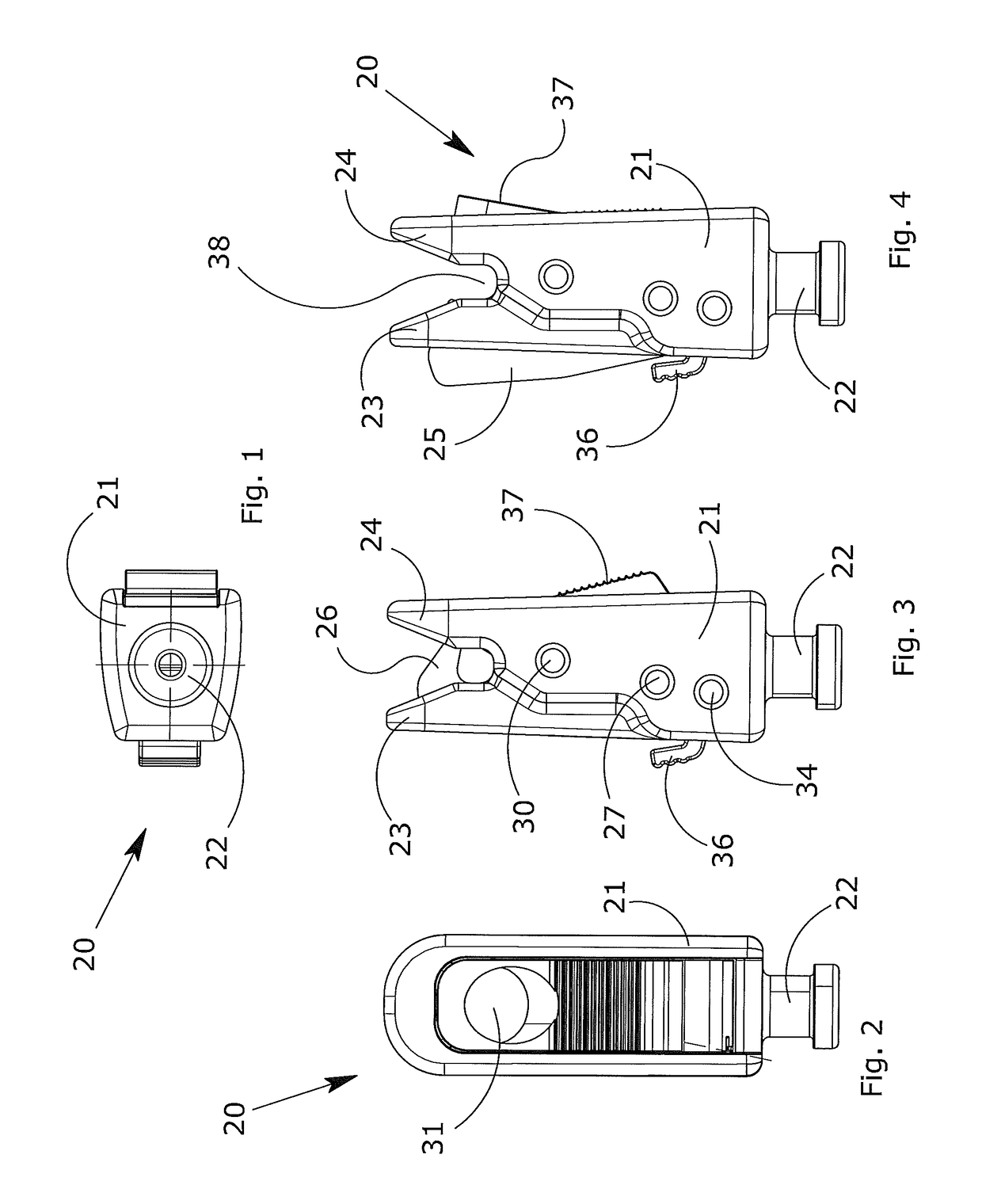
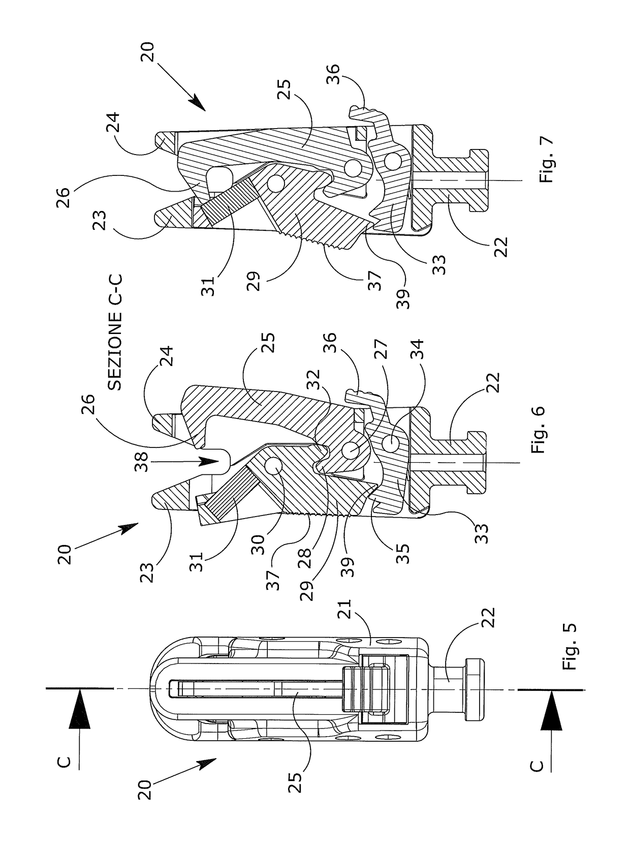
[0022]The self locking safety spring clip according to this invention comprises:[0023]a main body for fixing, for example, to the strap of a leash or to another retaining element for example with the hands, the main body being equipped with guide means which allow quick centring of the spring clip with the object to be attached, for example to the ring of a collar for reta...


PUM


Abstract

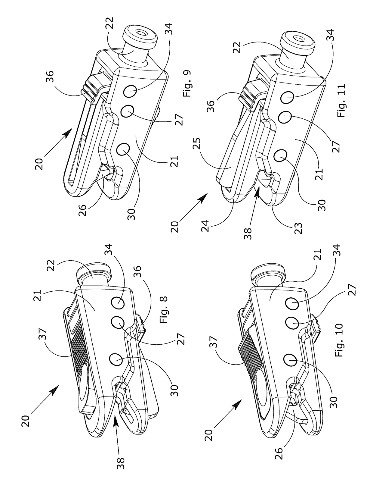
Described is a self locking safety spring clip including at least a main body (21) provided with an opening (38) designed to receive a ring. The main body (21) houses a first locking element (25) equipped at an end with a hook-shaped part or hook (26) and rotatable about a first pin (27) integral with the main body, as well as a second locking element (29) opposite the previous one, rotatable about a second pin (30) integral with the main body, the second locking element (29) being equipped with a magnetic element (31) designed to attract the ring thus facilitating the coupling and simultaneously the locking to the hook-shaped part or hook (26).

Description

TECHNICAL FIELD[0001]This invention relates to a self locking safety spring clip.[0002]It is an automatic coupling spring clip with can be used mainly but not exclusively for coupling the leash to the collars of pets, such as for example dogs, but also for many other applications, such as for example for uses in the sports, nautical or mountaineering sectors, or for other uses in which it is necessary to fasten a rope or the like to a ring or the like.[0003]Unlike the traditional solutions on the market, the spring clip according to the invention proposes that the coupling is performed in an almost automatic and self locking mode, that is, simply placing the gripping end next to the coupling element results in the instantaneous coupling in conditions of maximum safety, that is, preventing any possibility of release unless the opening system is used, which can be operated only by actuating a particular combination of conditions.[0004]This invention can be applied in the field of acce...

Claims


Application Information

Patent Timeline
Patent Type & Authority Patents(United States)
IPC IPC(8): F16B45/02F16B1/00A01K27/00
CPCF16B45/02F16B1/00A01K27/005F16B2001/0035F16B2200/83F16B45/034F16B45/026
Inventor VACCARI, CARLO
Owner FERPLAST
Learn More