Airflow restricting valve assembly

a valve assembly and airflow restriction technology, applied in the field of valve assembly, can solve the problems of air entering the path of fluid flow within the water supply line, water supply installation, functional valve types, etc., and achieve the effect of reducing the quantity of air remaining

Active Publication Date: 2015-02-03
FLUIDLYTIX LLC
View PDF35 Cites 7 Cited by
  • Summary
  • Abstract
  • Description
  • Claims
  • Application Information

AI Technical Summary

Benefits of technology

[0010]The present invention is directed to a valve assembly structured to eliminate or significantly reduce the presence of air traveling along a path of fluid flow and mixed with water within...

Problems solved by technology

As is well recognized, there are occasional breakdowns, repairs, maintenance procedures, malfunctions, etc., of public water utility facilities and/or other water distribution and sup...

Method used


Image

  • Airflow restricting valve assembly
  • Airflow restricting valve assembly
  • Airflow restricting valve assembly

Examples


Embodiment Construction

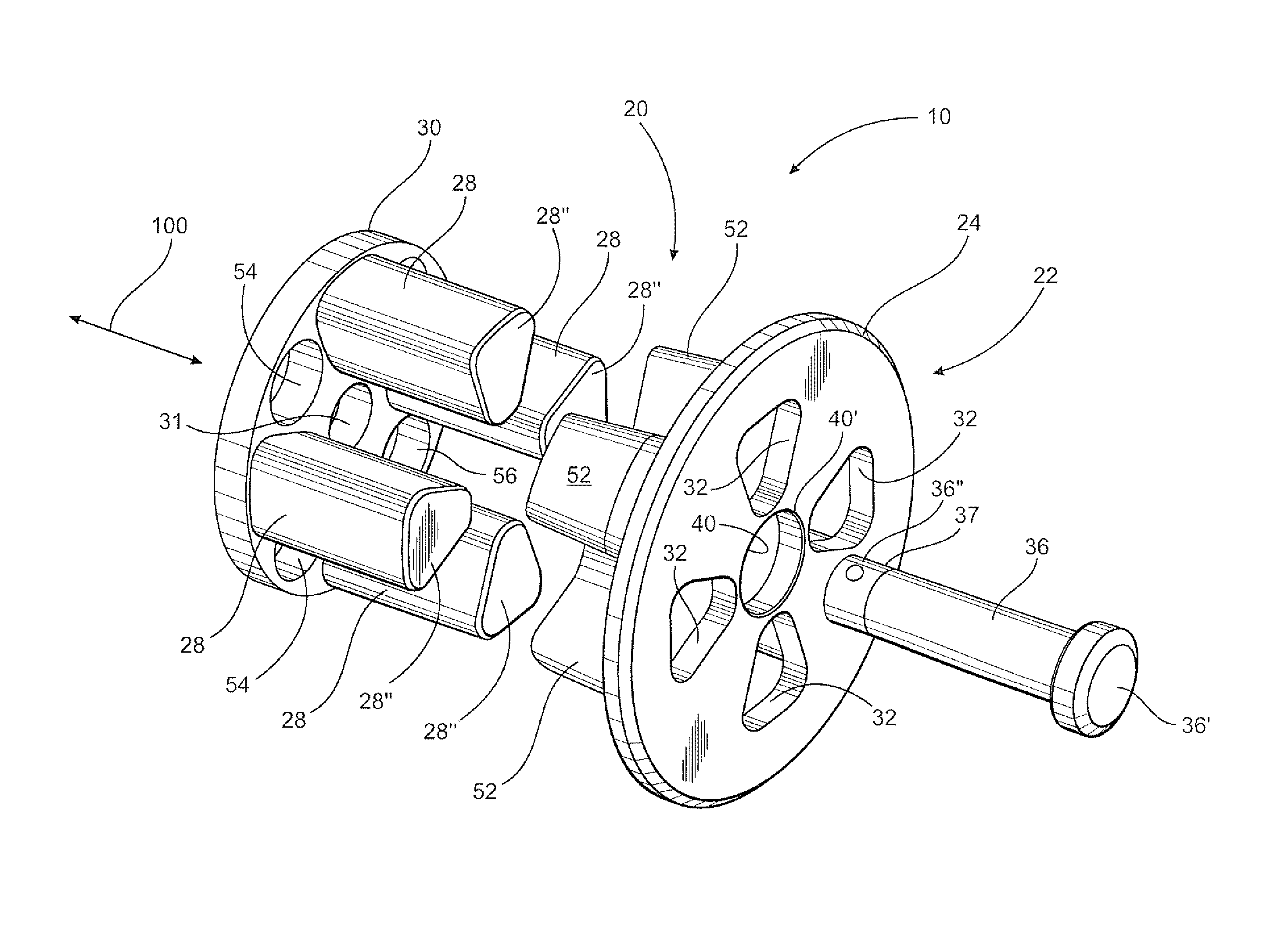
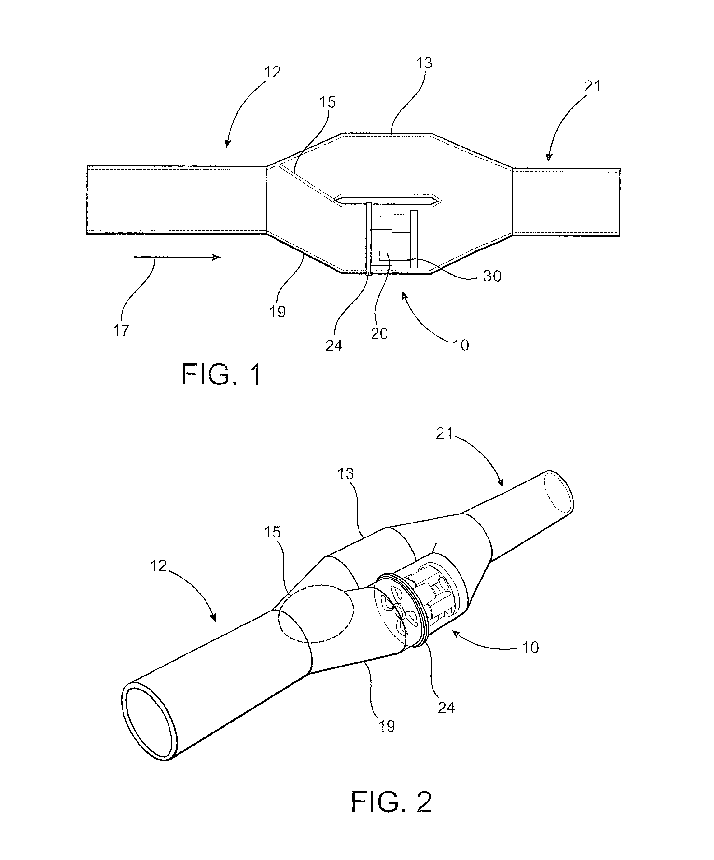
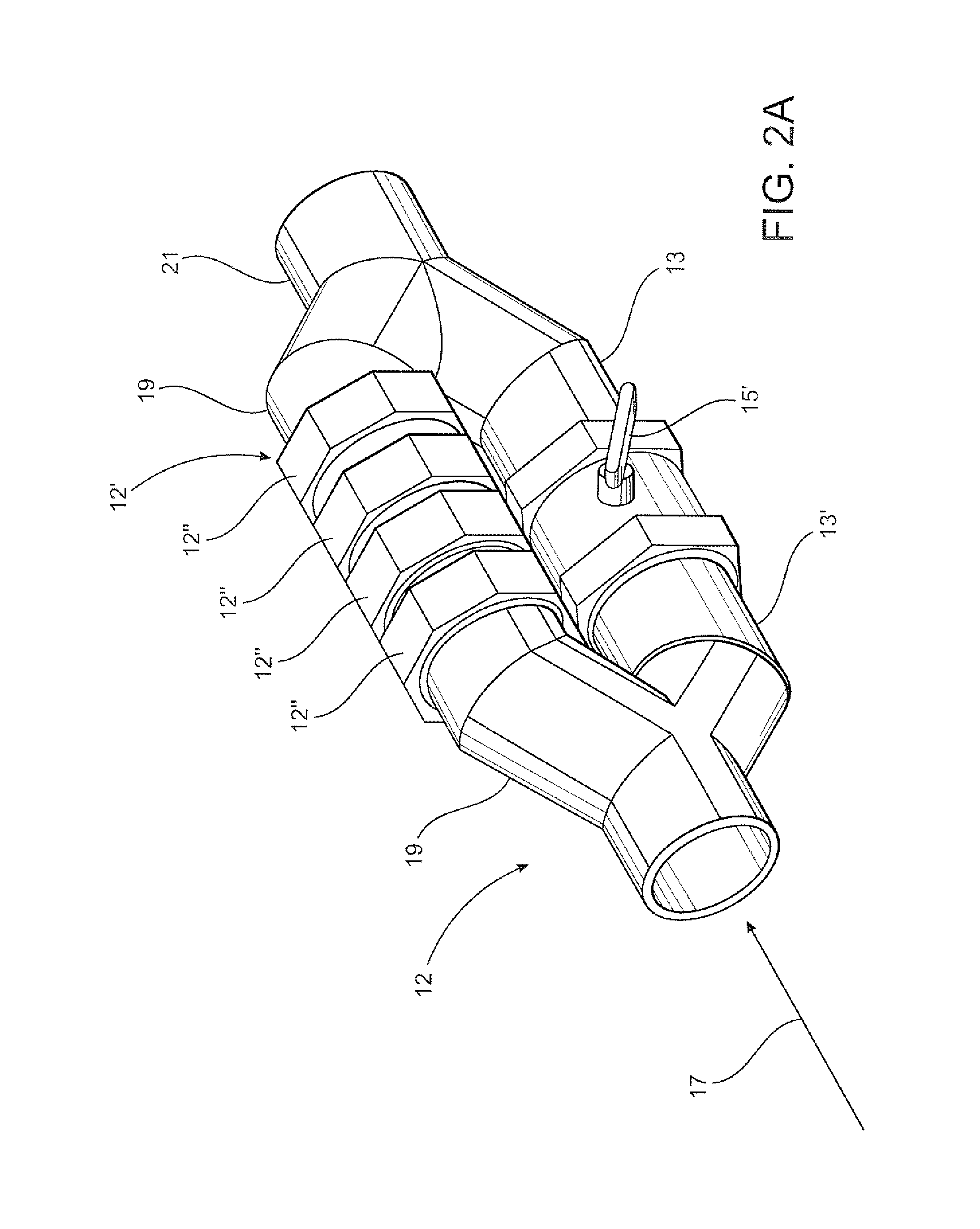
[0032]As represented in the accompanying drawings, the present invention is directed to a valve assembly generally indicated as 10 structured to be inserted within a water supply or delivery line generally indicated as 12 in the schematic representations of FIGS. 1-2A. The valve assembly 10 is structured to eliminate or significantly reduce the amount of air passing along a path of fluid flow within the interior of the water supply line 12, prior to the flow of fluid reaching a downstream location, such as a water meter. Specific practical applications disclosed in FIGS. 1 and 2 include the water supply or delivery line 12 including a bypass segment 13 and a flap valve or other fluid directing structure 15. Accordingly, water will pass along a path of fluid flow on the interior of the supply line 12 in accord with the represented directional arrow 17.

[0033]The bypass 13 and the flow directing structure 15 are provided to divert the flow of fluid in order to facilitate the removal, r...


PUM


Abstract

A valve assembly is disposed within a water supply line upstream of a water meter or other delivery location and is structured to eliminate or significantly reduce the passage of air there through to the upstream location. A valve body includes a sealing portion sealing disposed within the supply line and in interruptive, exposed relation to a path of fluid flow there through. One or more valve members are biased into sealing relation to a plurality of valve seat openings formed in the sealing portion. A sufficient, predetermined biasing force is exerted on the valve members to maintain them into a sealing orientation with the valve seats, thereby preventing the opening of the valve members until a sufficient water pressure is exerted thereon by a flow water, from which the air has been removed, along the path of fluid flow. As a result, air included within the water flow supply line will be compressed and/or displaced and substantially prevented from passing independently or mixed with the flow of water downstream of the valve body.

Description

BACKGROUND OF THE INVENTION[0001]1. Field of the Invention[0002]This invention relates to a valve assembly disposed along a path of fluid flow within a water supply line. The valve assembly is structured to eliminate or significantly reduce the passage of air to a location downstream of the valve assembly, wherein the air may be in the form of air pockets or air segments or otherwise mixed and / or included in the path of fluid flow along which the water travels within the water supply line. As a result a downstream location of delivery, such as a water meter, will only register the actual quantity of water delivered and avoid any charges resulting from the passage of air through the meter.[0003]2. Description of the Related Art[0004]Approximately three and one-half billion people throughout the world have access to a water supply delivered to a domestic or commercial facility by a water supply line(s) in the form of pipes, conduits, etc. The origin of the water supply, especially in ...

Claims


Application Information

Patent Timeline
IPC IPC(8): F16K15/02
CPCF16K15/02Y10T137/87555Y10T137/7845Y10T137/7839F16K15/026
Inventor BOCOS, JUAN CARLOSBOCOS VILAR, JUAN CARLOS
Owner FLUIDLYTIX LLC
Why Eureka
Try Eureka