Air conditioner

a technology for air conditioners and air filters, applied in the field of air conditioners, can solve the problems of inapplicability or unrealistic technical disclosures, impaired energy conservation, and inability to implement or realistically disclose them, and achieve the effects of reducing noise, reducing draft resistance, and reducing the quantity of air discharg

Inactive Publication Date: 2007-03-06
DAIKIN IND LTD
View PDF11 Cites 81 Cited by
  • Summary
  • Abstract
  • Description
  • Claims
  • Application Information

AI Technical Summary

Benefits of technology

[0068]Therefore, when the opening area of the discharge duct 14 is increased, i.e., when the quantity of air discharge is increased, the distribution shutter 11 assumes a position at the region of the discharge duct 14 where the velocity of flow is low, so as to reduce draft resistance caused by the distribution shutter 11, thus ensuring air quantity with certainty and reducing noise due to a blown air. On the other hand, when the opening area of the discharge duct 14 is reduced, i.e., the quantity of air discharge is reduced, the distribution shutter 11 assumes a position at the upstream side region of the discharge duct 14, thus suppressing, to the extent possible, the disturbance of an air flow at a region of the outlet 4 located at the downstream side end of the discharge duct 14. As a result, it is allowed to prevent condensation from occurring at a portion of the indoor panel 2 adjacent to the outlet 4, and contamination from occurring at a ceiling surface due to the collision of the disturbed discharged air flow thereto.

Problems solved by technology

This has been causing, for example, a problem that temperature variations occur in the space to be air-conditioned to create an area inferior in comfort accompanied with draftiness, another problem that an area without the presence of a person is air-conditioned as with an area with the presence of a person, and still another problem that energy conservation is impaired because of the execution of unnecessary and needless air conditioning as a result of, for example, always running an air conditioning apparatus under a predetermined condition even though the heat load distribution in the space to be air-conditioned varies with time depending on criteria such as season, time of day and the number of people present in a room.
However, although the proposed prior-art techniques described above as well-known examples are theoretically thought to provide necessary functionality and make the expected effects obtainable, the technical disclosures thereof are not implementable or not realistic, and therefore, the fact is that the above-described techniques are not yet brought into practical use.

Method used


Image

  • Air conditioner
  • Air conditioner
  • Air conditioner

Examples


first embodiment

[0098]I: First Embodiment of Air Conditioning Apparatus

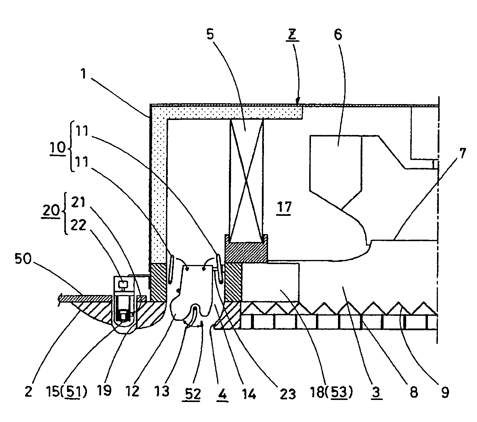
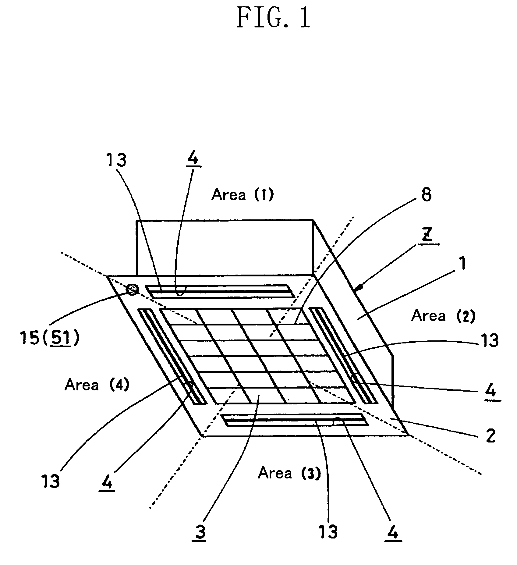
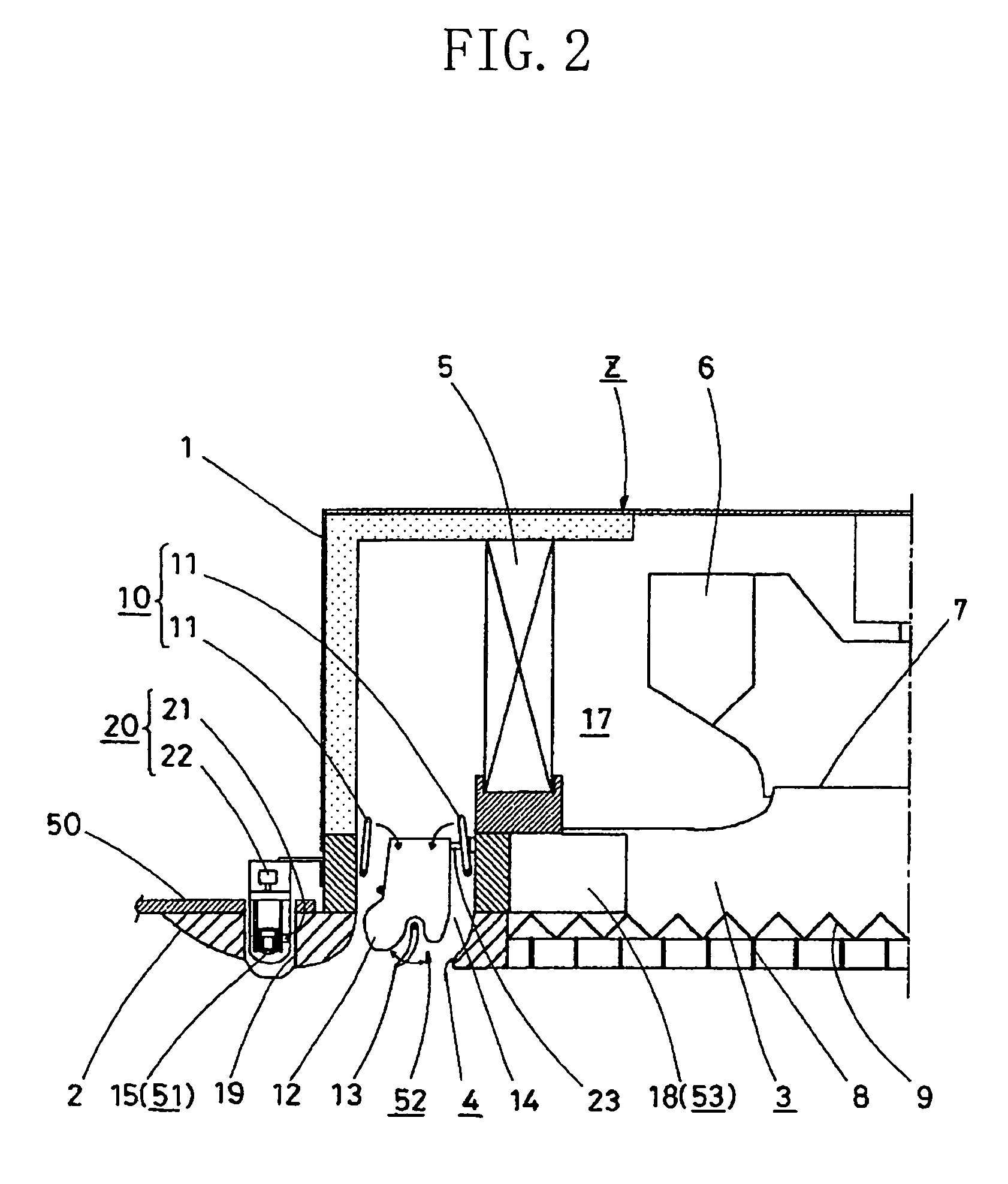
[0099]FIGS. 1 and 2 show an indoor unit Z of a separate type air conditioning apparatus as the first embodiment of an air conditioning apparatus according the present invention. The indoor unit Z is a ceiling-embedded type indoor unit embedded in a ceiling 50 above the inside of a room, and has a basic structure similar to a conventionally known one. Specifically, the indoor unit Z includes: a rectangular boxlike casing 1 embedded in the ceiling 50 so that the casing 1 is located above the ceiling 50; and a rectangular flat-shaped indoor panel 2 that is placed at an opening of a lower end of the casing 1 from the inside of the room. The indoor panel 2 is provided at its center with an inlet 3 formed by a rectangular opening. Provided outwardly of the inlet 3 are four outlets 4, 4, . . . that are formed by elongated rectangular openings so as to rectangularly surround the inlet 3, and that are each extended substantially parallel...

second embodiment

[0131]How the controller 18 carries out control will be described in summary by providing several exemplary controls, subsequent to the following description made about an air conditioning apparatus.

[0132]II: Second Embodiment of Air Conditioning Apparatus

[0133]FIGS. 3 and 4 show an indoor unit Z of a separate type air conditioning apparatus as the second embodiment of an air conditioning apparatus according to the present invention. This indoor unit Z is similar in basic configuration to the indoor unit Z according to the first embodiment, and is different from the indoor unit Z according to the first embodiment in that the indoor unit Z of the present embodiment is provided with not only the infrared sensor 15 but also an after-mentioned temperature and humidity sensor 16 as the detection means 51, since the indoor unit Z of the first embodiment is provided with only the infrared sensor 15 as the detection means 51.

[0134]Therefore, only the configuration of the temperature and hum...


PUM


Abstract

An operational air conditioning mode is allowed to set to a temperature uniformization mode and a spot air conditioning mode, and is selectively switched between these modes automatically by a control means (53) or manually. In such an embodiment, a comfortably air-conditioned state is obtained in all the areas of a space to be air-conditioned W during air conditioning performed in the temperature uniformization mode, and the comfort is ensured by intensively air-conditioning the surroundings of a person during air conditioning performed in the spot air conditioning mode. At the same time, since an unnecessary air conditioning is not provided to a region without the presence of a person, energy conservation is improved, for example, and thus the comfort of air conditioning and energy conservation are both achieved.

Description

[0001]This application is the national phase under 35 U.S.C. § 371 of PCT International Application No. PCT / JP02 / 13408 which has an International filing date of Dec. 20, 2002, which designated the United States of America.TECHNICAL FIELD[0002]The present invention relates to an air conditioning apparatus that is provided with: an inlet located at the center of the bottom face of an indoor unit; and a plurality of elongated rectangular outlets located to surround the periphery of the inlet, and that is installed such that the indoor unit is embedded in or hung from a ceiling.BACKGROUND ART[0003]For example, in order to provide air conditioning to a relatively large space to be air-conditioned such as a shop, a restaurant or an office in a building, an indoor unit of the type embedded in a ceiling or of the type hung from a ceiling has heretofore generally been disposed at a ceiling located above the space to be air-conditioned.[0004]In providing air conditioning to such a large space...

Claims


Application Information

Patent Timeline
Patent Type & Authority Patents(United States)
IPC IPC(8): F25D17/04F24F1/0047F24F1/0073F24F11/00F24F11/02F24F13/06F24F13/14F24F13/15F24F13/20
CPCF24F1/0007F24F1/0011F24F11/0034F24F13/06F24F11/0015F24F1/0022F24F2001/0037F24F2011/0064F24F2221/38F24F11/30F24F2110/20F24F2120/10F24F11/65F24F1/0047F24F13/1426F24F2013/1433F24F1/0073F24F11/46
Inventor KASAI, MASAYASHIOCHI, SUMIOAKIYAMA, RYUUJISHIGEMORI, KAZUHISA
Owner DAIKIN IND LTD
Why Eureka
Try Eureka