

Stator arrangement of rotary electric machine
- Summary
- Abstract
- Description
- Claims
- Application Information
AI Technical Summary
Benefits of technology
Problems solved by technology
Method used
Image

Examples
Embodiment Construction
[0027] A vehicle AC generator according to a preferred embodiment of the invention is described in detail with reference to the appended drawings.
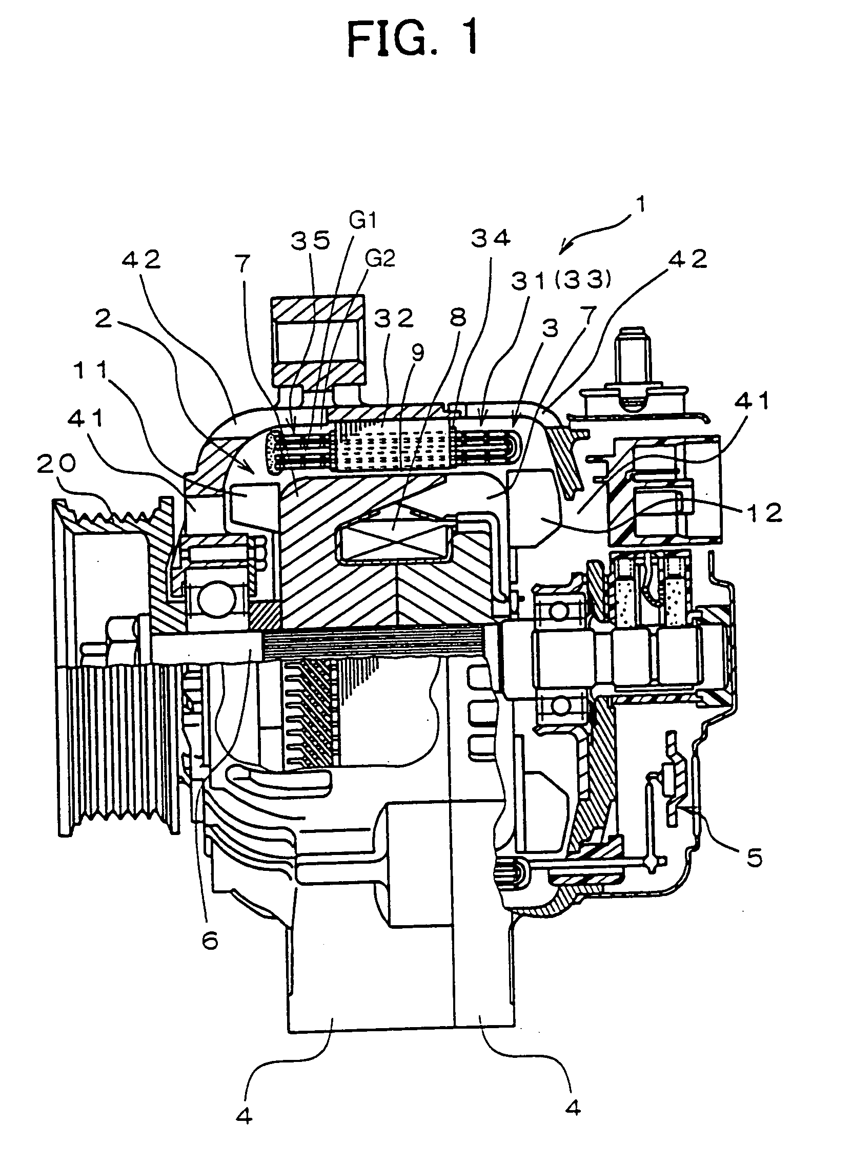
[0028] As shown in FIG. 1, the vehicle AC generator 1 according to the preferred embodiment is comprised of a rotor 2, a stator 3, a pair of frames 4, a rectifier unit 5, etc.
[0029] The rotor 2 is comprised of a field coil 8 having a cylindrically wound insulation-film-coated copper wire, a pair of pole cores 7, each having six craw poles, and a shaft 6. The shaft 6 penetrates the field coil 8 and the pair of claw poles. The claw poles envelop the field coil 8 from opposite ends thereof. A mixed-flow-type cooling fan 11 is welded to the front end of the pole core 7 to blow air from the front end in the axial and radial directions. A centrifugal cooling fan 12 is also welded to the rear end of the pole core 7 to blow air from the rear end in the radially outer direction.
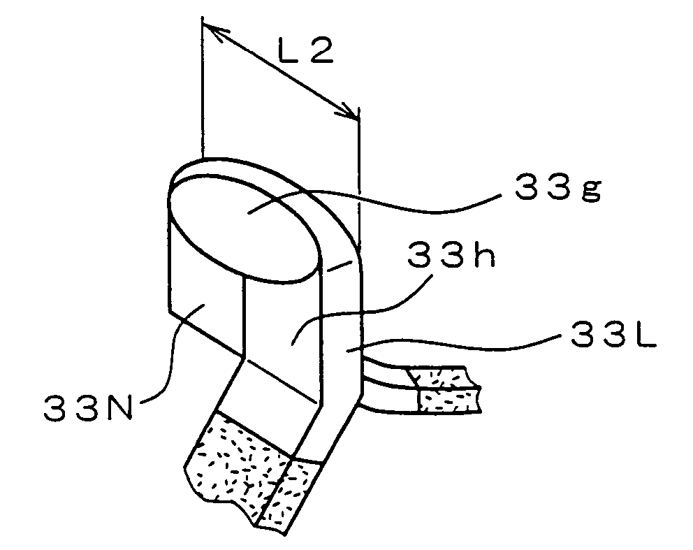
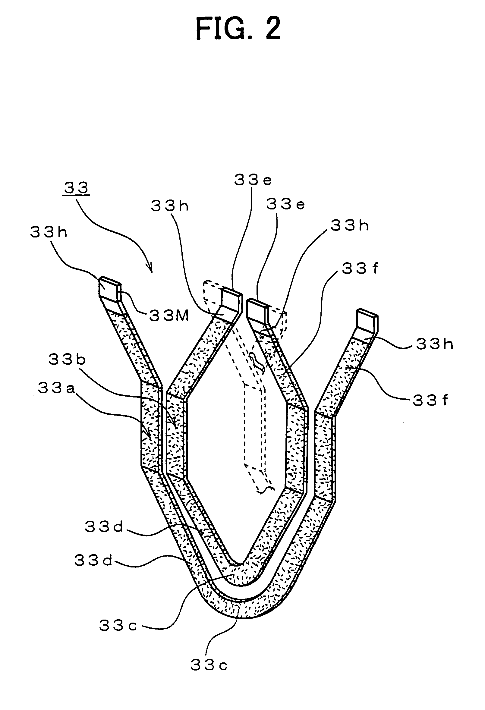
[0030] The stator 3 is comprised of a stator core 32, a stator windi...
PUM
| Property | Measurement | Unit |
|---|---|---|
| Length | aaaaa | aaaaa |
| Area | aaaaa | aaaaa |
Abstract
Description
Claims
Application Information