Heat dissipater and manufacturing method thereof

A manufacturing method and radiator technology, applied in the direction of cooling/ventilation/heating transformation, etc., can solve the problems of inability to provide good heat dissipation performance, limited number of heat dissipation fins, and inability to shorten the distance between heat dissipation fins, etc., to improve heat dissipation efficiency and simplify process, the effect of increasing the heat dissipation area

Active Publication Date: 2014-08-13
GIGA BYTE TECH CO LTD
View PDF6 Cites 4 Cited by
  • Summary
  • Abstract
  • Description
  • Claims
  • Application Information

AI Technical Summary

Problems solved by technology

[0005] In view of the above problems, the present invention is to provide a heat sink and its manufacturing method, thereby solving the problem that the conventional heat sink is limited by the processing

Method used


Image

  • Heat dissipater and manufacturing method thereof
  • Heat dissipater and manufacturing method thereof
  • Heat dissipater and manufacturing method thereof

Examples


Example Embodiment

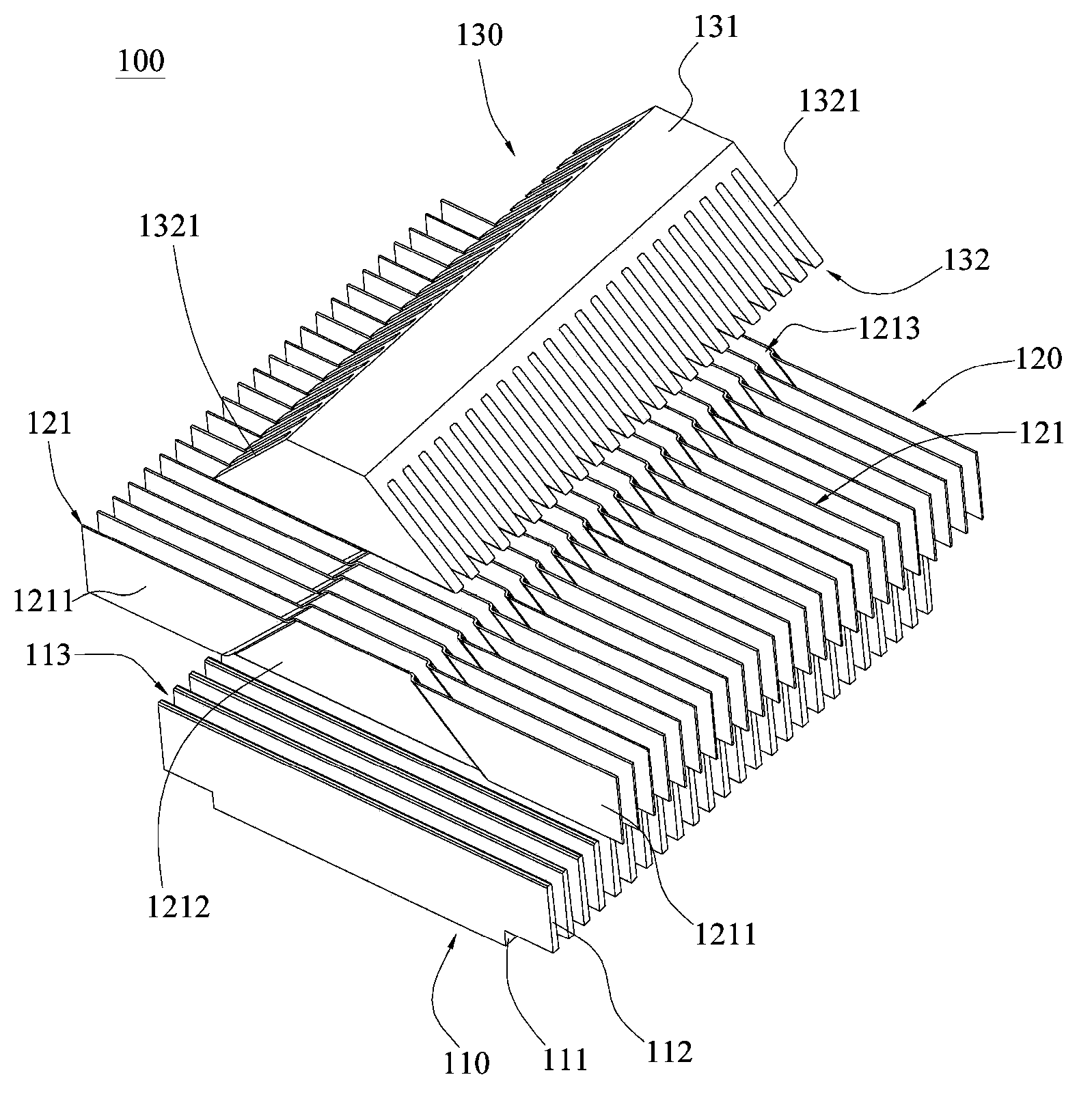
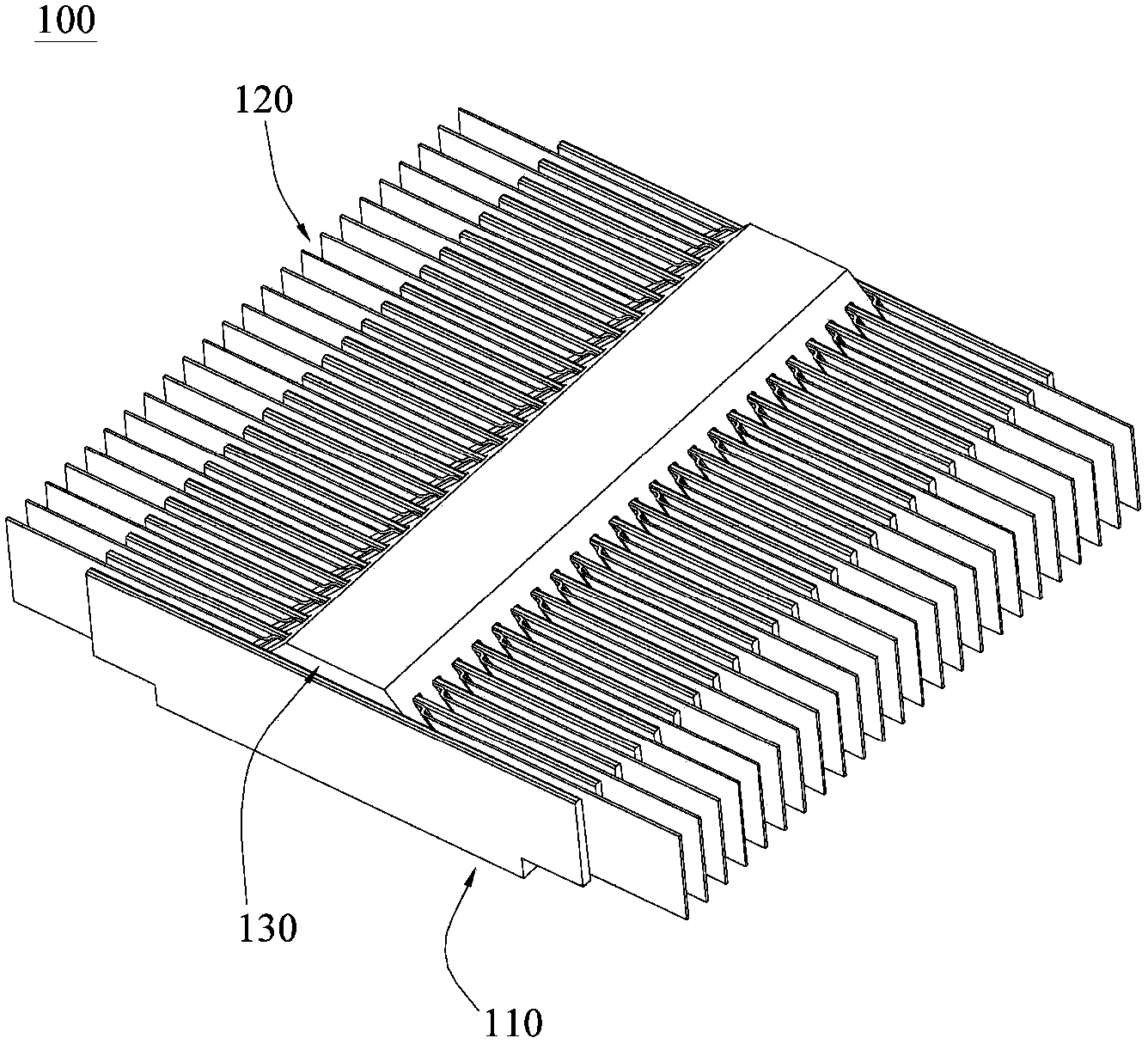
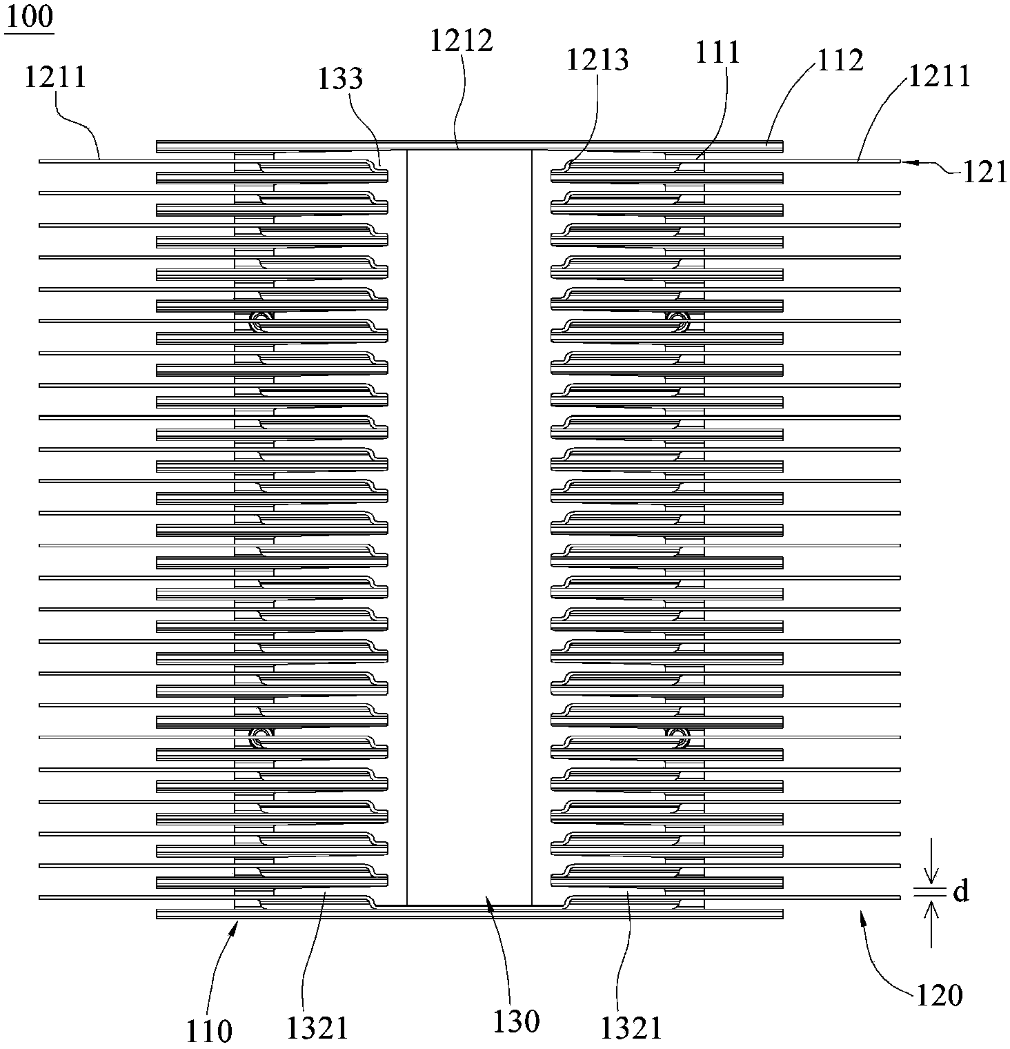
[0039] Such as Figure 1 to Figure 3 As shown, the heat sink 100 disclosed in the first embodiment of the present invention includes a base 110, a fin set 120, and a fastener 130. The base includes a bottom plate 111 and a plurality of first heat dissipation fins 112. A heat dissipation fin 112 is arranged on the bottom plate 111 at intervals, and a recess 113 is formed between adjacent first heat dissipation fins 112, wherein a plurality of first heat dissipation fins 112 are along a first direction (for example, the bottom plate 111 The long side direction) are arranged at intervals, and the opposite ends of each first heat dissipation fin 112 extend in a second direction perpendicular to the first direction (for example, the short side direction of the bottom plate 111), and extend beyond the bottom plate 111 Opposite two sides.

[0040] The fin set 120 includes a plurality of second heat dissipation fins 121. The length of the second heat dissipation fin 121 may be greater th...


PUM


Abstract

The invention relates to a heat dissipater and a manufacturing method thereof. The heat dissipater comprises a pedestal, a fin group, and a buckling member. The pedestal comprises a base plate and multiple first heat-dissipating fins. The fin group comprises multiple second heat-dissipating fins. The first heat-dissipating fins and the second heat-dissipating fins are arranged on the base plate in a staggered manner. The buckling member is combined with the pedestal and pushes the heat-dissipating segments of the multiple second heat-dissipating fins to be abutted against the first heat-dissipating fins. Thus, the heat-dissipating segments of the second heat-dissipating fins are apart from the first heat-dissipating fins. By means the above configuration mode, the heat dissipater is provided with high-density heat-dissipating fins so as to improve the heat-dissipating efficiency of the heat dissipater.

Description

【Technical field】 [0001] The invention relates to a radiator and a manufacturing method thereof, in particular to a radiator for heat dissipation of electronic components and a manufacturing method thereof. 【Background technique】 [0002] With the rapid development of the electronic industry, the power of electronic components such as central processing unit (CPU) or graphics processing unit (graphic processing unit (GPU)) used in electronic devices has been greatly increased. The density is also getting higher and higher, relatively resulting in a substantial increase in the heat generated by the electronic components during operation, which often results in an increase in the temperature inside the electronic components themselves and the system in which they are configured. At the same time, with the rapid accumulation of heat, the performance of the electronic components is reduced, and it is easy to cause the computer system to crash, or even the electronic components t...

Claims


Application Information

Patent Timeline
IPC IPC(8): H05K7/20
Inventor 毛黛娟
Owner GIGA BYTE TECH CO LTD
Why Eureka
Try Eureka