Firearm sight with retractable sunshade

a retractable sunshade and firearm technology, applied in the field of firearm sights, can solve the problems of inaccurate aiming or visual interference of users, lack of environmental protection from rain, dust and lens glare, and installation speed, etc., to achieve better environmental protection, compact design, and small size

Active Publication Date: 2018-11-27
SELLMARK CORP
View PDF54 Cites 14 Cited by
  • Summary
  • Abstract
  • Description
  • Claims
  • Application Information

AI Technical Summary

Benefits of technology

[0006]It is a general object of the present invention to provide an improved sight for firearms. This and other objects of the present invention are achieved by providing a sight body including a clamp at its lower extent for removably securing the sight to a portion of a firearm. An upwardly facing surface is disposed on the sight body above the clamp and a housing projects above the upwardly facing portion, the housing containing a lens assembly. A shade is carried by the sight body, the shade movable along the sight body from a retracted position in which the shell is at least partially contained by the housing, and an extended position in which the shell extends over the upwardly facing surface.

Problems solved by technology

The lack of environmental protection from rain, dust, and lens glare is a shortcoming of reflector sights.
This optical interference can cause inaccurate aiming or visual interference for the user.
These devices, however, typically cannot be installed quickly (in a matter of seconds), causing the shooter to lose sense of their environment.
They also cannot be easily stored due to their bulky designs so if removed in the field they must be uncomfortably stored in the user's pocket or in a bag.
Finally, current covers are designed to be installed and remain on the sight at all times; however, use of a sunshade creates a “tunnel vision” effect which obstructs the user's field of view and impairs their situational awareness.

Method used


Image

  • Firearm sight with retractable sunshade
  • Firearm sight with retractable sunshade
  • Firearm sight with retractable sunshade

Examples


Embodiment Construction

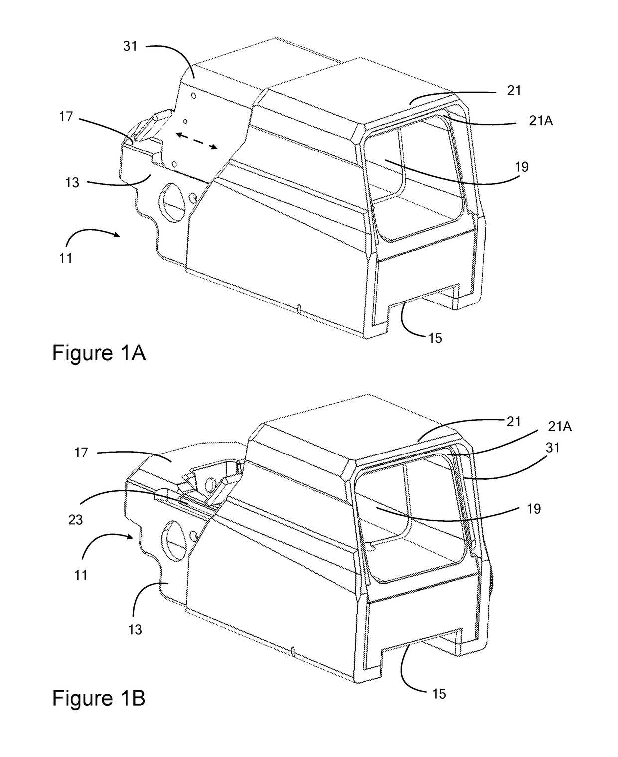
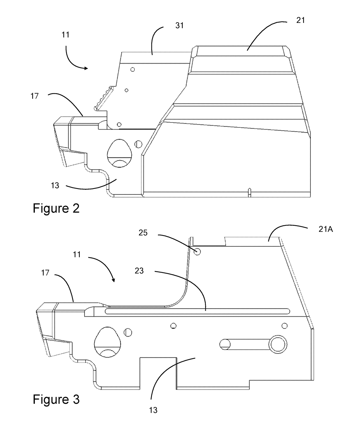
[0017]Referring now to the Figures, and in particular to FIGS. 1A, 1B, and 2, a firearm sight 11 according to one embodiment of the present invention is illustrated. Sight 11 is preferably of the reflex or reflector type and comprises a sight body 13, which has a clamp 15 at its lower extent for attachment to a mounting rail (11 mm or 0.375 inch dovetail or Picatinny or Weaver rail) on a firearm. Sight 11 is secured or attached to a rail on the receiver or barrel of a firearm in alignment with the bore of the weapon to provide a means of precisely aiming at targets.

[0018]At an upper extent of sight body 13, parallel to and generally opposite clamp 15, are a generally flat, upwardly facing surface 17 and a lens assembly 19 contained or housed in a housing 21. Housing 21 projects above surface 17. As can be seen in FIG. 1A, surface 17 is not truly flat, but multi-level and contains recesses for various aspects of sight 11, thus it is described as “generally flat.”

[0019]In a preferred ...


PUM


Abstract

A firearm sight comprises a sight body including a clamp at its lower extent for removably securing the sight to a portion of a firearm. An upwardly facing surface is disposed on the sight body above the clamp and a housing projects above the upwardly facing portion, the housing containing a lens assembly. A shade is carried by the sight body, the shade movable along the sight body from a retracted position in which the shell is at least partially contained by the housing, and an extended position in which the shell extends over the upwardly facing surface.

Description

BACKGROUND OF THE INVENTION1. Field of the Invention[0001]The invention relates to firearm sights and more particularly to reflex or reflector sights.2. Summary of the Prior Art[0002]Conventional reflector or reflex sights generally comprise a front lens designed to reflect the aiming dot through an open optical path. This design of reflector sights, compared to the similar “red dot” sight, helps achieve a smaller, more compact design. The design of a red dot sight, although typically larger in size, utilizes a closed (enclosed) optical path which provides better environmental protection and reduction in lens glare and reflections.[0003]The lack of environmental protection from rain, dust, and lens glare is a shortcoming of reflector sights. In bright lighting conditions, it is common for the top surface of a reflector sight to be a visible reflection when looking through the lens of the sight. This optical interference can cause inaccurate aiming or visual interference for the user...

Claims


Application Information

Patent Timeline
Patent Type & Authority Patents(United States)
IPC IPC(8): F41G1/30F41G1/06F41G1/38F41G1/04
CPCF41G1/065F41G1/30F41G1/383F41G1/04
Inventor HORTON, JONATHANCHEN, TIANLIANGPISCHKE, ANDREW
Owner SELLMARK CORP
Why Eureka
Try Eureka