Fluid pressure cylinder

a technology of fluid pressure cylinder and plug, which is applied in the direction of fluid-pressure actuator, etc., can solve the problems of plug loosening, plug falling off to the interior of the cylinder tube, and insufficient sealing between the closing member and the axial hole, etc., and achieves the effect of sufficient sealing of the plug

Active Publication Date: 2018-12-04
KYB CORP
View PDF14 Cites 0 Cited by
  • Summary
  • Abstract
  • Description
  • Claims
  • Application Information

AI Technical Summary

Benefits of technology

[0011]An object of the present invention is to ensure a sufficient sealability of a plug that closes a rod inner passage formed in a piston rod and to prevent the plug from falling off to an interior of a cylinder tube.

Problems solved by technology

Therefore, there is a risk that adequate sealing may not be achieved between the closing member and the axial hole if there is a large machining error during processing of the assembly hole.
However, in the case in which the plug is attached by being screwed into the axial hole, there is a risk that, the plug may be loosened and fall off to the interior of the cylinder tube (the bottom-side chamber) due to repetitive action, on both end surfaces of the plug, of hydraulic pressure that is guided to the head-side chamber and the bottom-side chamber when the hydraulic cylinder is operated.

Method used


Image

  • Fluid pressure cylinder
  • Fluid pressure cylinder
  • Fluid pressure cylinder

Examples


first embodiment

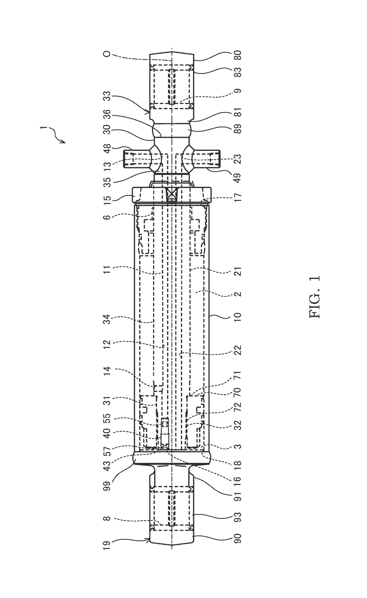
[0021]A hydraulic cylinder 1 serving as the fluid pressure cylinder shown in FIG. 1 includes a cylindrical cylinder tube 10, a piston 70 that partitions the interior of the cylinder tube 10 into a head-side chamber 2 and a bottom-side chamber 3, and a piston rod 30 that is linked with the piston 70 and projects out from a first end of the cylinder tube 10.

[0022]The head-side chamber 2 is provided on the head side at which the piston rod 30 projects out from the cylinder tube 10 and is defined between the piston 70 and a cylinder head 15, which will be described below. The bottom-side chamber 3 is provided on the bottom side at which the piston rod 30 does not project out from the cylinder tube 10 and is defined between the piston 70 and a bottom bracket 90, which will be described below.

[0023]The hydraulic cylinder 1 is operated so as to extend / contract by movement of the piston rod 30 relative to the cylinder tube 10 in the axial direction by working oil pressure (working-fluid pre...

second embodiment

[0055]Next, a second embodiment of the present invention will be described with reference to FIG. 6. Differences from the first embodiment will mainly be described below, while configurations that are same as those of the fluid pressure cylinder of the first embodiment are assigned the identical reference signs and descriptions thereof will be omitted.

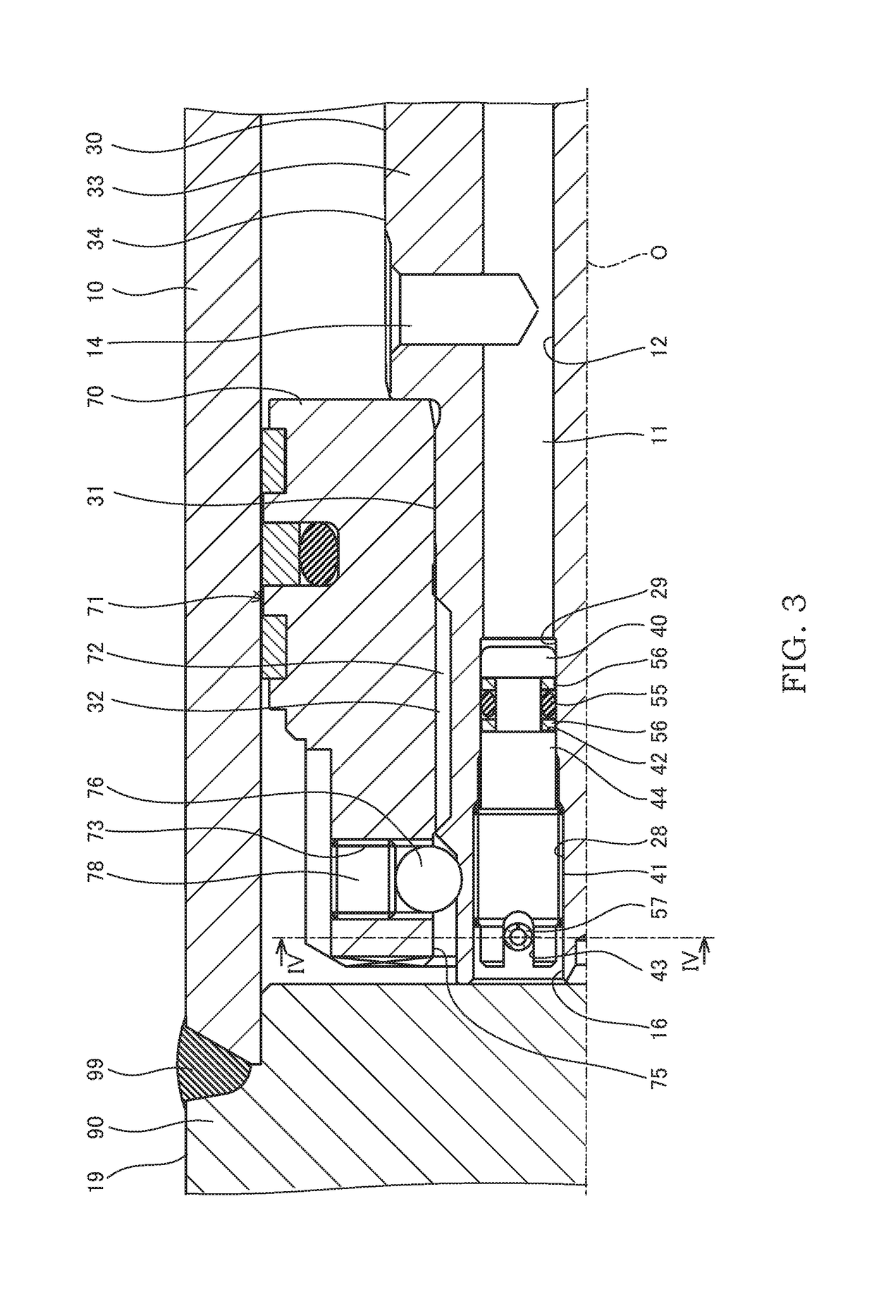
[0056]In the first embodiment, the pin 57 is disposed inside the piston 70, and the pin 57 is prevented from falling off by the inner circumferential surface 75 of the piston 70. In contrast, in the second embodiment, the rotation of the piston assembly 71 is locked by engaging the pin 57 with the piston 70.

[0057]Engagement portions 77 that engage with the pin 57 are formed on the piston 70 of the piston assembly 71. The engagement portions 77 are formed of two holes that are formed in the piston 70 so as to sandwich the lateral hole 25 formed in the piston rod 30. Both end portions of the pin 57 are inserted into the engagement portio...


PUM


Abstract

A hydraulic cylinder includes a rod inner passage that is formed in a piston rod along an axial direction and communicates a fluid pressure source and an interior of a cylinder tube; a plug that is inserted from an open end that opens to the interior of the cylinder tube of the rod inner passage; a lateral hole that is formed in the piston rod along a radial direction and extends so as to cross the rod inner passage; and a pin that is inserted into the lateral hole. In the piston rod, an inner-circumference screw portion is formed on an inner circumference of the rod inner passage, and on the plug, an outer-circumference screw portion that is screwed into the inner-circumference screw portion and an engagement portion that is engaged with the pin and locks rotation of the plug are formed.

Description

TECHNICAL FIELD[0001]The present invention relates to a fluid pressure cylinder that is operated so as to extend / contract by working-fluid pressure guided from a working-fluid pressure source.BACKGROUND ART[0002]JP2003-166508A discloses a hydraulic cylinder in which a first passage and a second passage are formed in a piston rod.[0003]In this hydraulic cylinder, an interior of a cylinder tube into which the piston rod is inserted is partitioned into a head-side chamber and a bottom-side chamber by a piston that is linked to the piston rod. When the hydraulic cylinder is operated so as to extend, pressurized working oil from a hydraulic power source is supplied to the bottom-side chamber through the first passage, and the working oil in the head-side chamber is returned to a tank of the hydraulic power source through the second passage. When the hydraulic cylinder is operated so as to contract, the pressurized working oil from the hydraulic power source is supplied to the head-side c...

Claims


Application Information

Patent Timeline
Patent Type & Authority Patents(United States)
IPC IPC(8): F15B15/14
CPCF15B15/1447F15B15/1457F15B15/1461F15B15/149
Inventor KOBAYASHI, NOBUYUKI
Owner KYB CORP
Why Eureka
Try Eureka