
Interlock device for preventing close during insertion or withdraw on circuit breaker in switch board

a technology of interlocking device and switch board, which is applied in the direction of air-break switch, high-tension/heavy-dress switch, basic electric elements, etc., can solve the problems of increasing work time and maintenance time, and achieve the effect of enhancing stability

Active Publication Date: 2018-12-11
LSIS CO LTD
View PDF9 Cites 0 Cited by
  • Summary
  • Abstract
  • Description
  • Claims
  • Application Information

AI Technical Summary

Benefits of technology

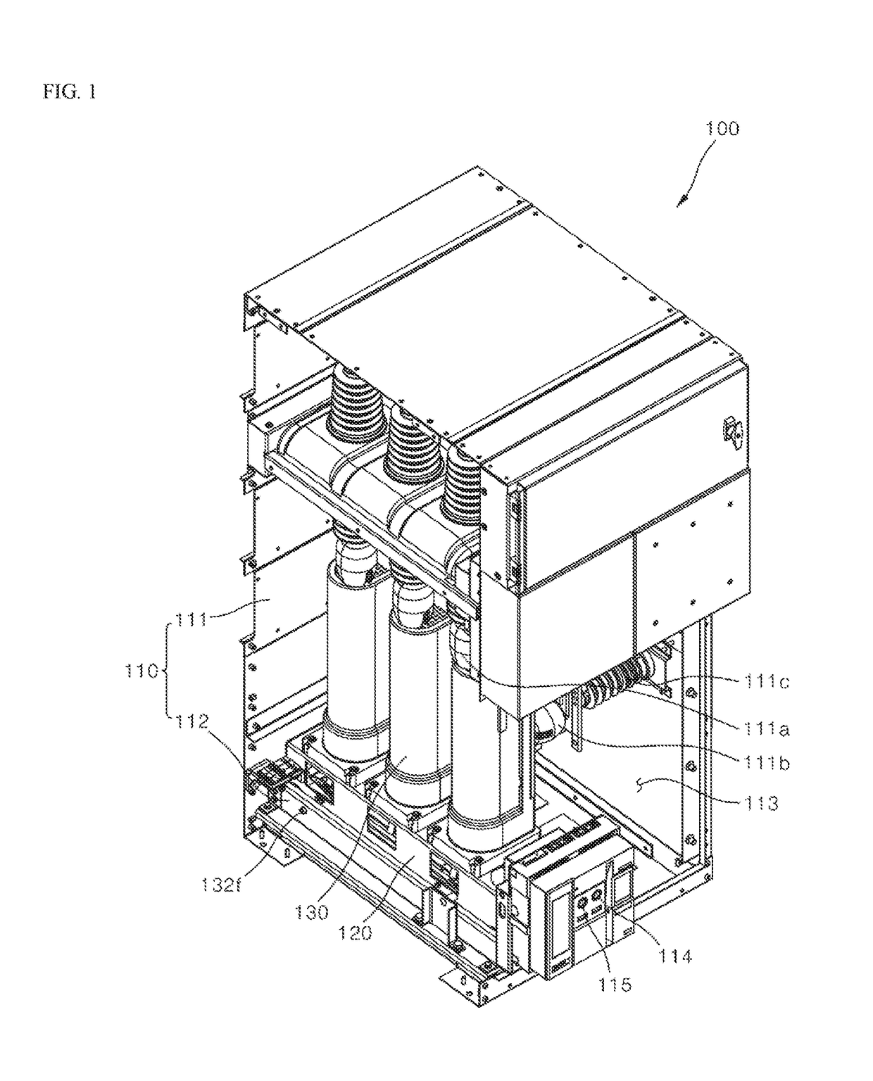
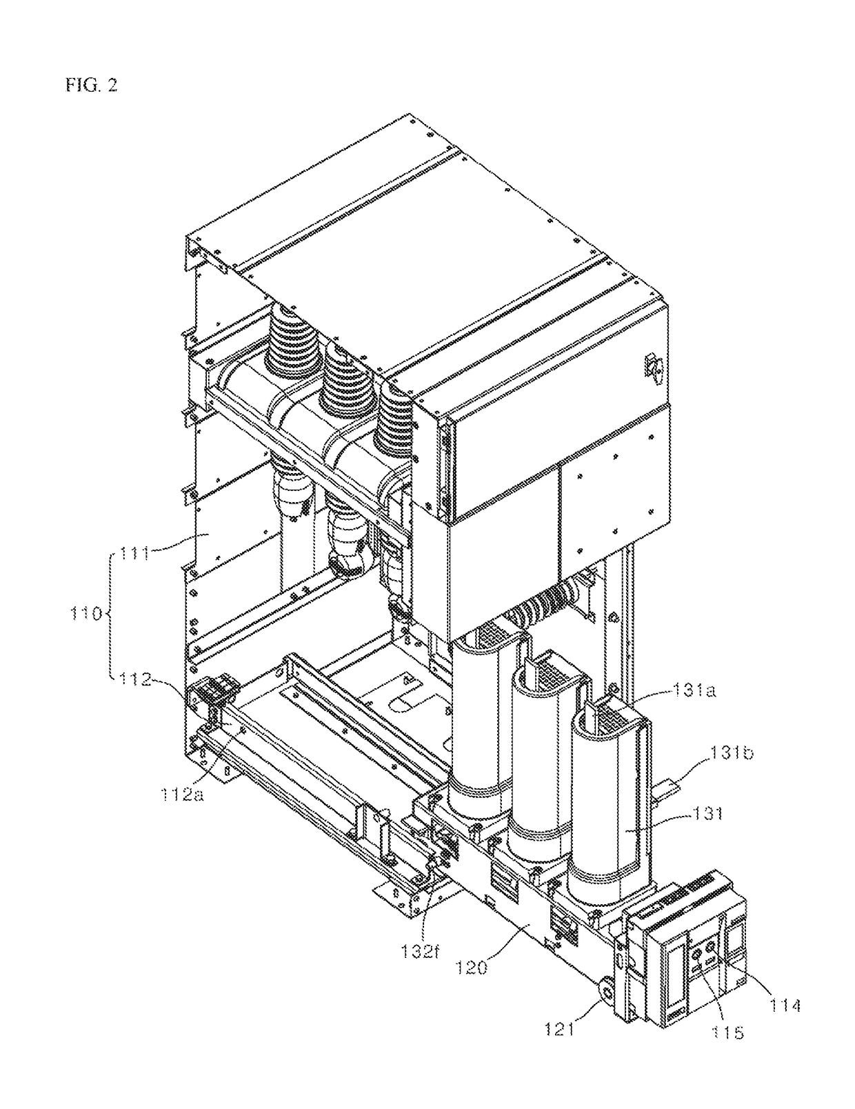
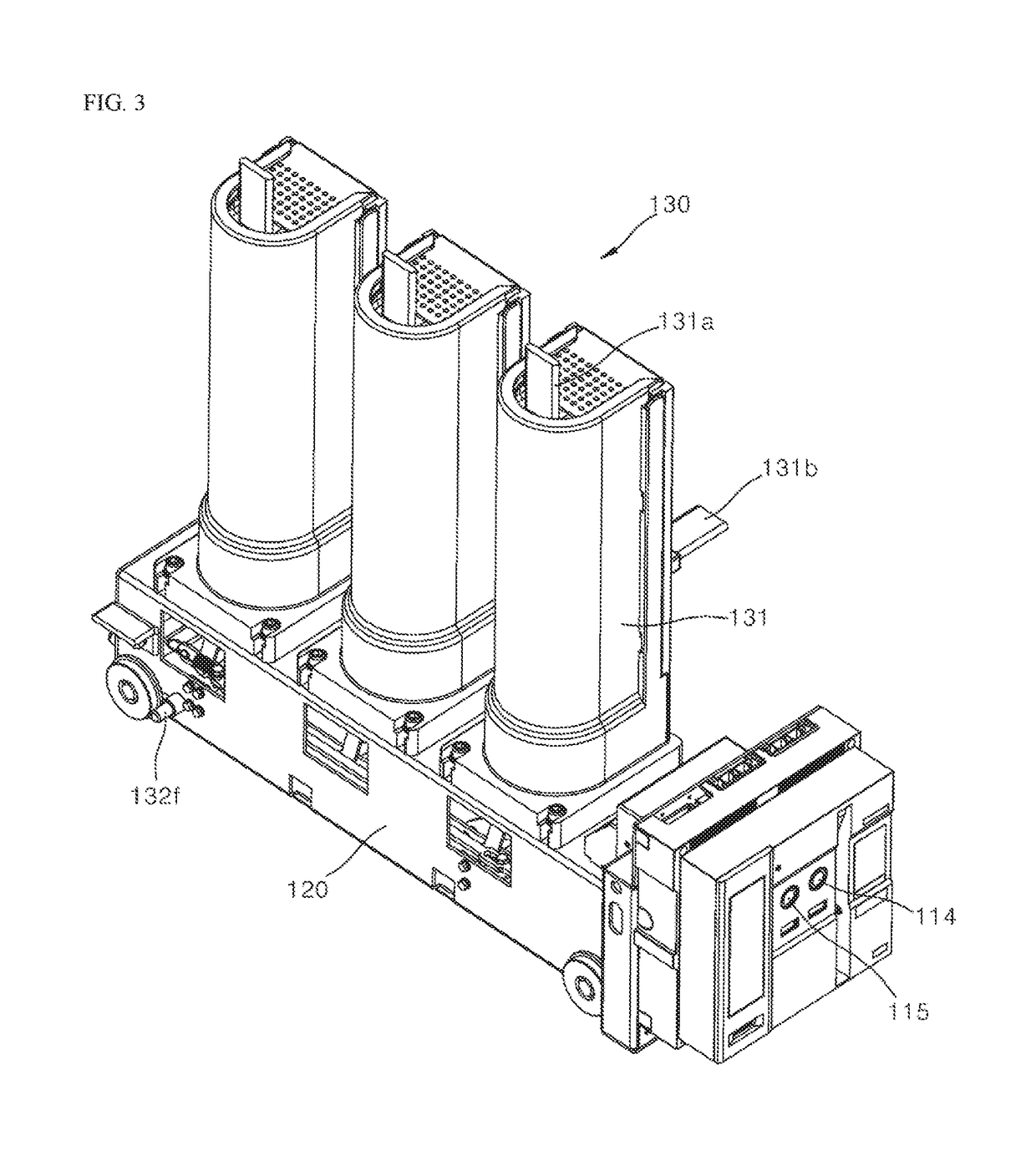
[0009]It is an object of the present disclosure to provide an interlock device for preventing insertion or withdrawal of a circuit breaker which is structurally improved to prevent the circuit breaker put into the switch board from being withdrawn from or inserted into the switch board to prevent an accident caused by incomplete contact between the switch board and the circuit breaker.
[0012]According to the present disclosure, a circuit breaker includes an insertion / withdrawal interlock device inserted into an interruption hole in the switch board, and thus the circuit breaker cannot be removed from the switch board while power is applied. Accordingly, an accident caused by incomplete contact between the power source of the switch board and the terminal of the circuit breaker may be prevented, and the circuit breaker may be prevented from being broken due to electrical damages.
[0013]In addition, when the circuit breaker is inserted into the switch board, the OFF button is kept pressed by the insertion / withdrawal interlock device, and therefore power is not applied even if the ON button for putting in the circuit breaker is inadvertently pressed during insertion of the circuit breaker. Therefore, stability may be enhanced.

Problems solved by technology

For the fixed circuit breaker, the terminals fixed to the power source side and the load side need to be disconnected to perform maintenance, which increases work time and maintenance time.

Method used


Image

  • Interlock device for preventing close during insertion or withdraw on circuit breaker in switch board
  • Interlock device for preventing close during insertion or withdraw on circuit breaker in switch board
  • Interlock device for preventing close during insertion or withdraw on circuit breaker in switch board

Examples


Embodiment Construction

[0019]The above objects, features and advantages will become apparent from the detailed description with reference to the accompanying drawings. Embodiments are described in sufficient detail to enable those skilled in the art in the art to easily practice the technical idea of the present disclosure. Redundant description and detailed descriptions of well-known functions or configurations may be omitted in order not to unnecessarily obscure the gist of the present disclosure. Hereinafter, an interlock device for preventing insertion or withdrawal of a circuit breaker in a switch board according to preferred embodiments of the present disclosure will be described in detail with reference to the accompanying drawings. Throughout the drawings, like reference numerals refer to like elements. Embodiments of the disclosure are provided to more fully describe the present disclosure to those skilled in the art. It will be appreciated that for clarity of illustration, the shapes and dimensi...


PUM


Abstract

The present disclosure relates an interlock device for preventing insertion or withdrawal of a circuit breaker into or from a switch board having an ON button and an OFF button and including a switch board body provided with a housing and a rail having an interruption hole formed on one side surface thereof, a carriage movable back and forth along the rail of the switch board body, and the circuit breaker including a main body installed on the carriage and inserted into or withdrawn from the switch board body, the interlock device comprising an interlock rod protruding toward one side to set or release a pressed state, wherein the interlock rod is set in or released from the pressed state and inserted into or disengaged from the interruption hole when the main body is put in or tripped.

Description

CROSS-REFERENCE TO RELATED APPLICATIONS[0001]This application claims the priority of Korean Patent Application No. 10-2016-0125119 filed on Sep. 28, 2016, in the Korean Intellectual Property Office, the disclosure of which is hereby incorporated by reference in its entirety.BACKGROUND1. Technical Field[0002]The present disclosure relates to an interlock device for preventing insertion or withdrawal of a circuit breaker in a switch board, which is capable of preventing the circuit breaker from being withdrawn from or inserted into the switch board after the circuit breaker is put into the circuit breaker.2. Description of the Related Art[0003]Generally, a vacuum circuit breaker is built in the switchboard and is capable of cutting off a fault current on the line and allowing a rated current to be applied. The vacuum circuit breaker is a device that quickly isolates a circuit by extinguishing, in a vacuum container, an arc generated in the event of opening / closing of a normal load and...

Claims


Application Information

Patent Timeline
Patent Type & Authority Patents(United States)
IPC IPC(8): H02B11/133H02B11/167H01H33/46H01H33/66
CPCH02B11/133H02B11/167H01H33/46H01H33/66
Inventor LEE, HAN-JOOAHN, KIL-YOUNGYANG, HONG-IK
Owner LSIS CO LTD
Learn More