
Organic light-emitting device, method for manufacturing same, display device and illuminator

a technology of organic electroluminescent elements and display devices, which is applied in the direction of discharge tubes/lamp details, discharge tubes luminescent screens, other domestic objects, etc., can solve the problems of high luminance, difficult to increase the lifetime of organic el elements, and practically impossible to apply conventional organic electroluminescent materials and organic electroluminescent elements of conventional construction to televisions. , to achieve the effect of high luminance and durability, excellent luminance and durability

Inactive Publication Date: 2006-09-28
JOLED INC
View PDF10 Cites 2 Cited by
  • Summary
  • Abstract
  • Description
  • Claims
  • Application Information

AI Technical Summary

Benefits of technology

[0006] In view of the foregoing and other problems, it is a first object of the present invention to increase the luminance and / or lifetime of an organic electroluminescent element by structurally improving it. It is a second object of the present invention to provide a fabrication method of an organic electroluminescent element with high luminance and / or an extended lifetime. It is a third object of the present invention to provide a display device with high luminance and / or an extended lifetime. It is a fourth object of the present invention to provide a lighting system with high luminance and / or an extended lifetime.

Problems solved by technology

Thus, it is not easy to increase the lifetime of organic EL elements as compared with laser emitting diodes (LEDs), which employ inorganic materials for the emissive layer.
Thus, it has been practically impossible to apply conventional organic electroluminescent materials and organic electroluminescent elements of conventional constructions to television, which requires high luminance, and to lighting systems, which require extremely high luminance.

Method used


Image

  • Organic light-emitting device, method for manufacturing same, display device and illuminator
  • Organic light-emitting device, method for manufacturing same, display device and illuminator
  • Organic light-emitting device, method for manufacturing same, display device and illuminator

Examples


Embodiment Construction

Embodiments of First Invention Group

[0032] The following describes the contents and preferred embodiments of the first invention group of the present invention.

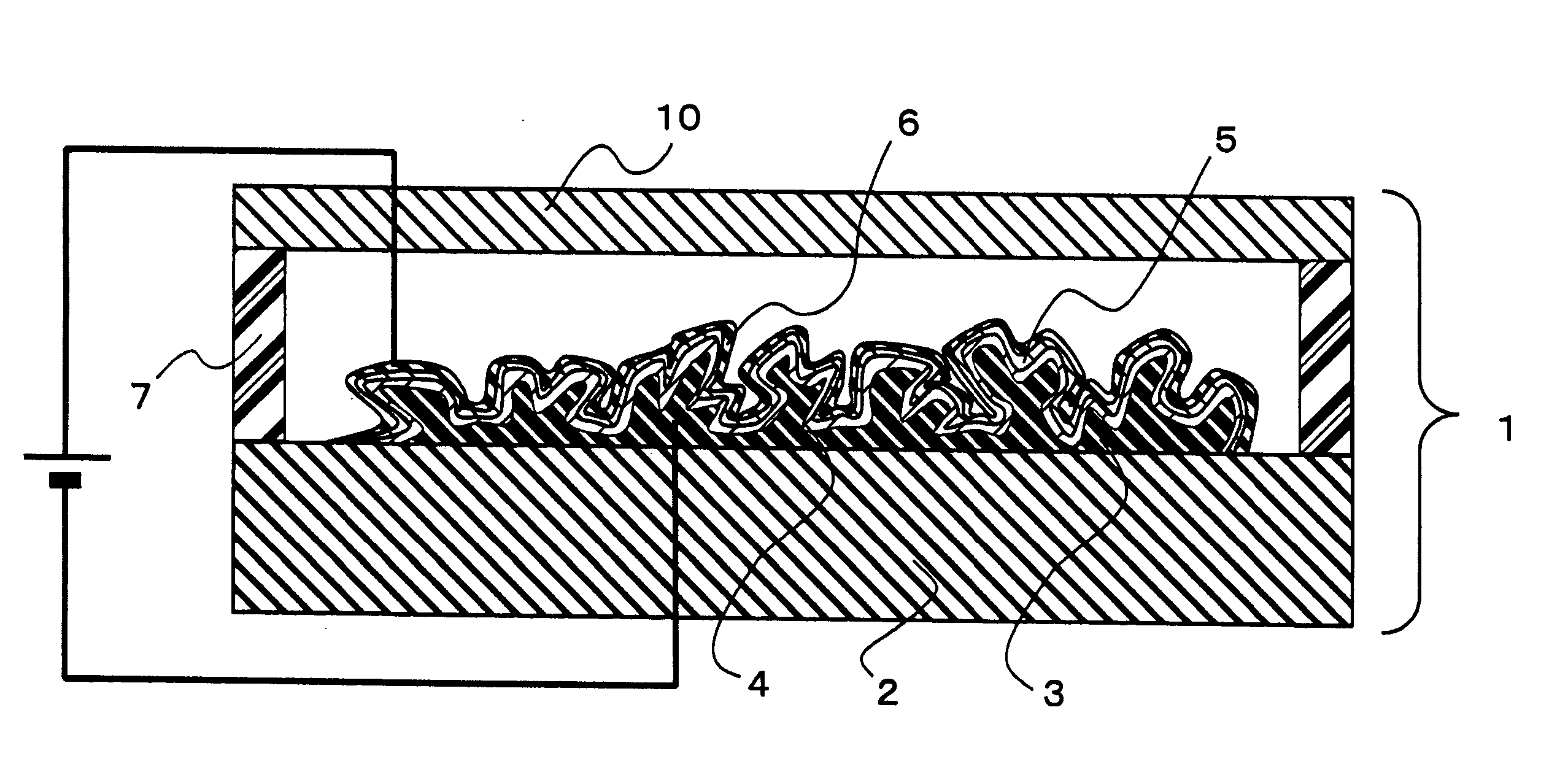
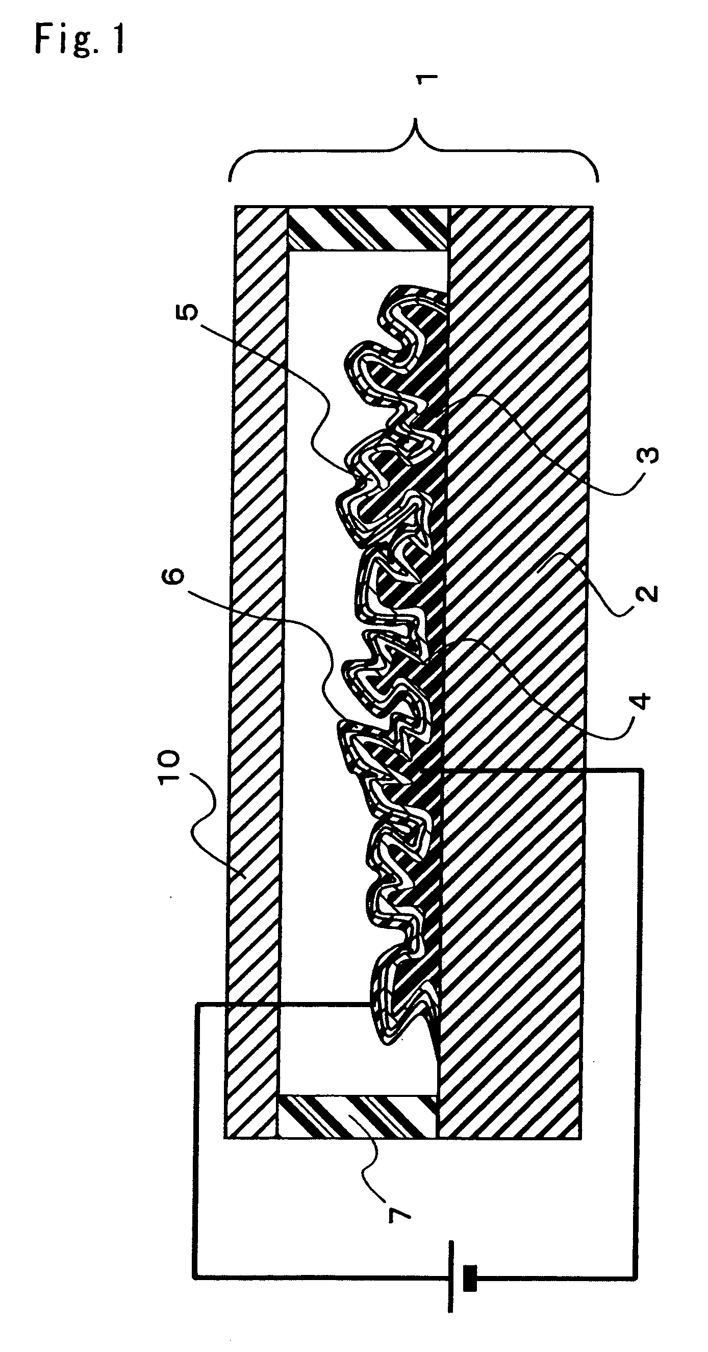
[0033] An organic electroluminescent element that is the embodiment of the first invention group of the present invention, and a method of fabricating thereof will be described with reference to FIG. 1. FIG. 1 is a section of an organic electroluminescent element 1 according to the present invention.

[0034]

[0035] A first electrode having a multidimensionally meandering surface shape was formed in any of the following methods (A)-(D). It should be noted that the formation method of the first electrode is not limited to the following examples.

[0036] (A) A metal was dissolved and solidified in an inert gas atmosphere by using a high-voltage / high-frequency dissolving device in accordance with modified Czochralski processing. Thus, the surface of the lump of metal was processed into a multidimensionally meandering surface shape...


PUM

PropertyMeasurementUnit
Angleaaaaaaaaaa
Thicknessaaaaaaaaaa
Shapeaaaaaaaaaa

Abstract

An organic electroluminescent element has a substrate, a first electrode formed above the substrate, an emissive layer, and a second electrode formed above the emissive layer. In the first electrode, at least a surface opposite to the other surface facing the substrate has a multidimensionally meandering surface shape. The emissive layer includes an organic electroluminescent material and is formed along the multidimensionally-meandering-shaped surface of the first electrode. In the emissive layer, a surface facing the first electrode and the other surface opposite to the first-electrode-facing surface each have a multidimensionally meandering surface shape. The organic electroluminescent element of the present invention is used in an electroluminescent (EL) type display device as a pixel that is controlled individually for light emission. Also, the organic electroluminescent element of the present invention is used as a light source of an electroluminescent (EL) type lighting system. As a result, an organic electroluminescent element with high luminance and an organic electroluminescent element with a long lifetime are provided, and an EL display device and an EL lighting system using such elements are provided.

Description

TECHNICAL FIELD [0001] The present invention relates to organic electroluminescent elements, display devices and lighting systems using such organic electroluminescent elements. More particularly, the invention relates to the shape of an emissive layer in an organic electroluminescent element. BACKGROUND ART [0002] Organic electroluminescent elements (organic EL elements) are viewed as the promising display elements of the next generation in that such elements operate at a voltage of as low as 10 volts or less, are capable of realizing various colors emitted by using organic compounds of different connective structures, and have high electroluminescent efficiency. In recent years, with the development of organic electroluminescent elements, their luminance and electroluminescent efficiency have become applicable to display devices. [0003] Typical fabrication methods of such organic electroluminescent elements include a step of forming by the sputtering technique a transparent electr...

Claims


Application Information

Patent Timeline
IPC IPC(8): H05B33/26H01L27/32H01L51/52H05B33/06H05B33/10H05B33/14
CPCH01L27/3244H01L51/5012H01L51/5203Y10S428/917H10K59/12H10K50/11H10K59/805H10K50/805
Inventor WAKITA, NAOHIDENISHIYAMA, SEIJI
Owner JOLED INC
Learn More