Backlight unit and liquid crystal display device

a backlight unit and liquid crystal display technology, which is applied in the direction of lighting and heating apparatus, instruments, optical elements, etc., can solve the problems of reducing the display quality of the liquid crystal display device, reducing the light from the light source 201, etc., and achieves the effect of improving the illumination and simple arrangemen

Inactive Publication Date: 2014-11-18
SHARP KK
View PDF15 Cites 0 Cited by
  • Summary
  • Abstract
  • Description
  • Claims
  • Application Information

AI Technical Summary

Benefits of technology

[0021]A backlight unit in accordance with the present invention is an edge light type backlight unit including: a light guide plate; and a light source provided so as to face one end surface of the light guide plate, said edge light type backlight unit causing light that has entered the light guide plate through the one end surface to be emitted in the form of plane emission from one main surface of the light guide plate, an opposite end surface of the light guide plate, which opposite end surface is opposite to the one end surface of the light guide plate, having one or more protrusion(s) protruding in a peak direction of light that is emitted from the light source, and being constituted by (i) two or more inclined surfaces each of which is inclined relative to a direction perpendicular to the one main surface or (ii) one or more curved surface(s) curved relative to the direction perpendicular to the one main surface. Therefore, it is possible to provide a planar light source unit in which luminance has been improved with a simple arrangement.

Problems solved by technology

As a result, light from the light source 201 is not fully utilized.
This causes another problem of reducing display quality of the liquid crystal display device 200.

Method used


Image

  • Backlight unit and liquid crystal display device
  • Backlight unit and liquid crystal display device
  • Backlight unit and liquid crystal display device

Examples


Embodiment Construction

[0029]The following description discusses, with reference to the drawings, one embodiment of a liquid crystal display device in accordance with the present invention. Note, however, that the present invention is not limited to the following embodiment.

[0030](Arrangement of Liquid Crystal Display Device 100)

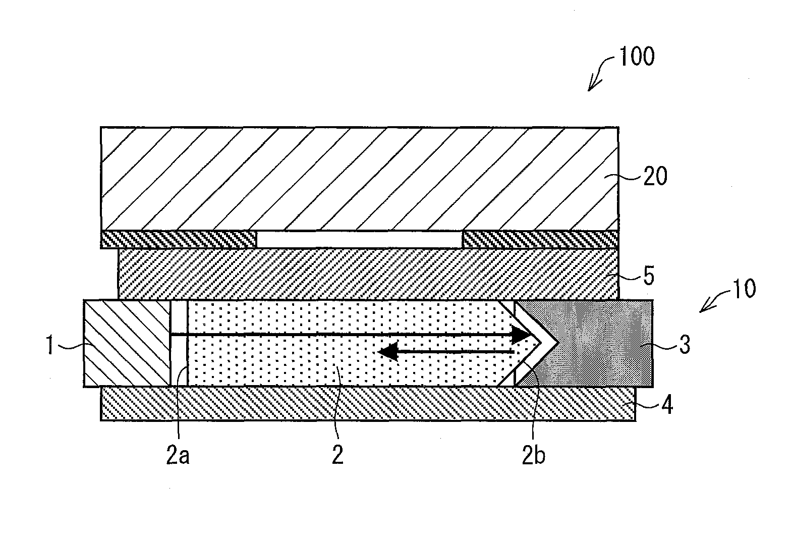
[0031]The following description discusses a schematic arrangement of the liquid crystal display device 100 with reference to FIG. 1. FIG. 1 is a cross-sectional view schematically showing an arrangement of the liquid crystal display device 100 of the present embodiment.

[0032]The liquid crystal display device 100 includes (i) a backlight unit 10 and (ii) a liquid crystal panel 20 provided on top of the backlight unit 10. Note here that the liquid crystal panel 20 can be a known liquid crystal panel, and is not limited to a particular kind.

[0033]The backlight unit 10 includes a light source 1, a light guide plate 2, a frame 3, a reflective sheet 4, and an optical sheet 5. The backli...


PUM

PropertyMeasurementUnit
thicknessaaaaaaaaaa
shapeaaaaaaaaaa
light energy lossaaaaaaaaaa

Abstract

A liquid crystal display device (100) of the present invention includes an edge light type backlight unit (10) and a liquid crystal panel (20). The backlight unit (10) includes a light guide plate (2) and a light source (1) that emits light to a light entrance end surface (2a) of the light guide plate (2). An opposite end surface (2b), of the light guide plate (2), which is opposite to the light entrance end surface (2a), is shaped to have one or more triangular shape(s) or one or more rounded shape(s) in a cross section both in a thickness direction of the light guide plate (2) and in a peak luminance direction of light from the light source (1). Light parallel to the peak luminance direction, which light is from the light source (1), is suitably reflected without being scattered by an inclined surface of the opposite end surface (2b).

Description

TECHNICAL FIELD[0001]The present invention relates to an edge light type backlight unit and a liquid crystal display device including the edge light type backlight unit.BACKGROUND ART[0002]There are many liquid crystal display devices each of which contains a backlight unit to backlight a panel so as to realize a bright display screen.[0003]In recent years, since mobile devices, such as mobile phones are becoming thinner, liquid crystal display devices included in the mobile devices are also required to be thinner. In order to meet this demand, there has been proposed an edge light type (side light type) backlight unit.[0004]The following description discusses a conventional edge light type backlight unit with reference to FIG. 6. FIG. 6 is a cross-sectional view showing a liquid crystal display device 200 which includes a backlight unit 210. The backlight unit 210 includes (i) a light guide plate 202 that is provided so as to face a liquid crystal panel 220, (ii) a light source 201...

Claims


Application Information

Patent Timeline
Patent Type & Authority Patents(United States)
IPC IPC(8): G02F1/1335F21S2/00
CPCG02B6/0045F21S2/00G02F1/133605
Inventor HIRAYAMA, YOSHINOBUTANAKA, SHIGENORIARAKI, RYOH
Owner SHARP KK
Why Eureka
Try Eureka