
Light-emitting device, and lighting system, and image display using same

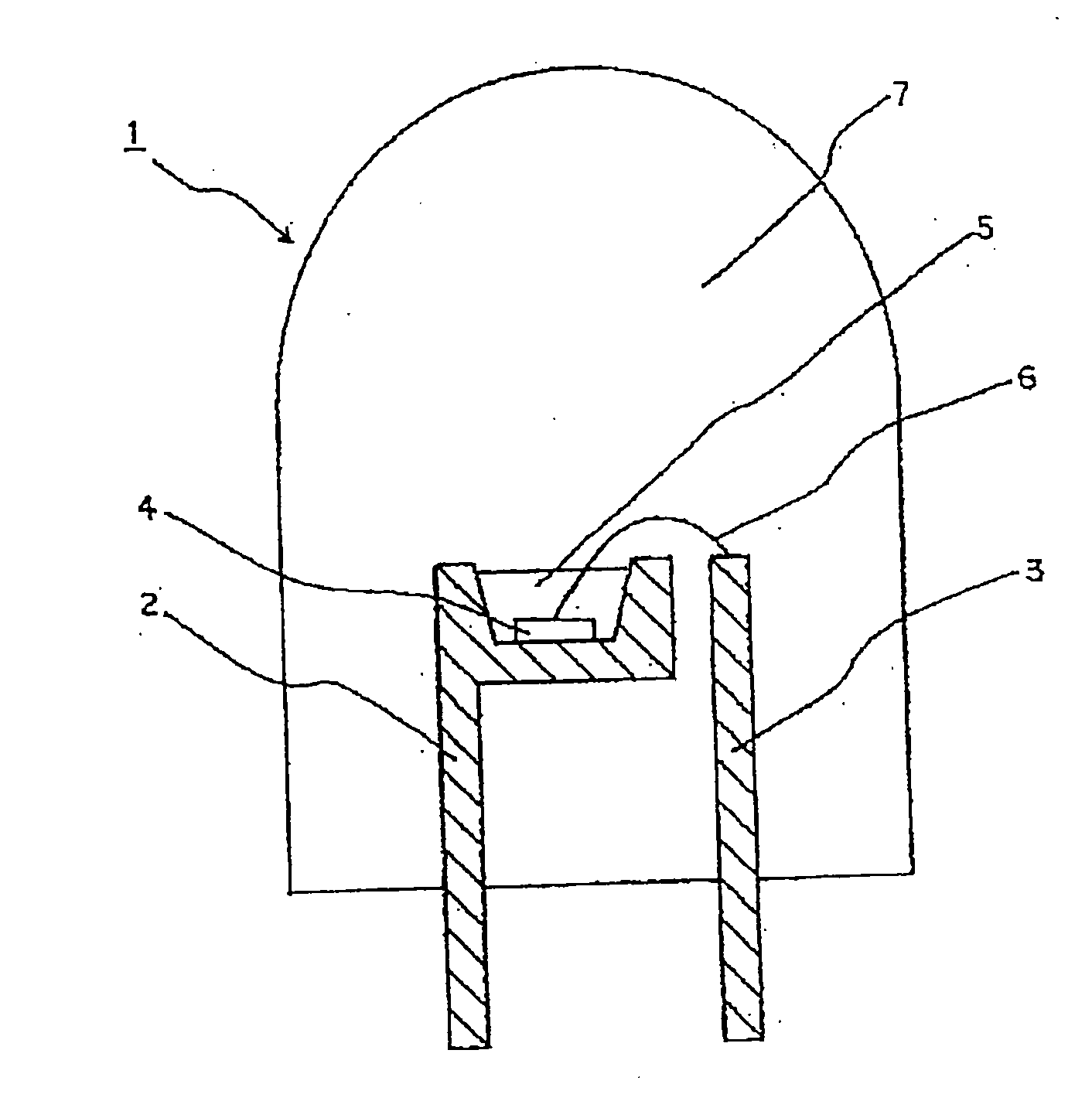
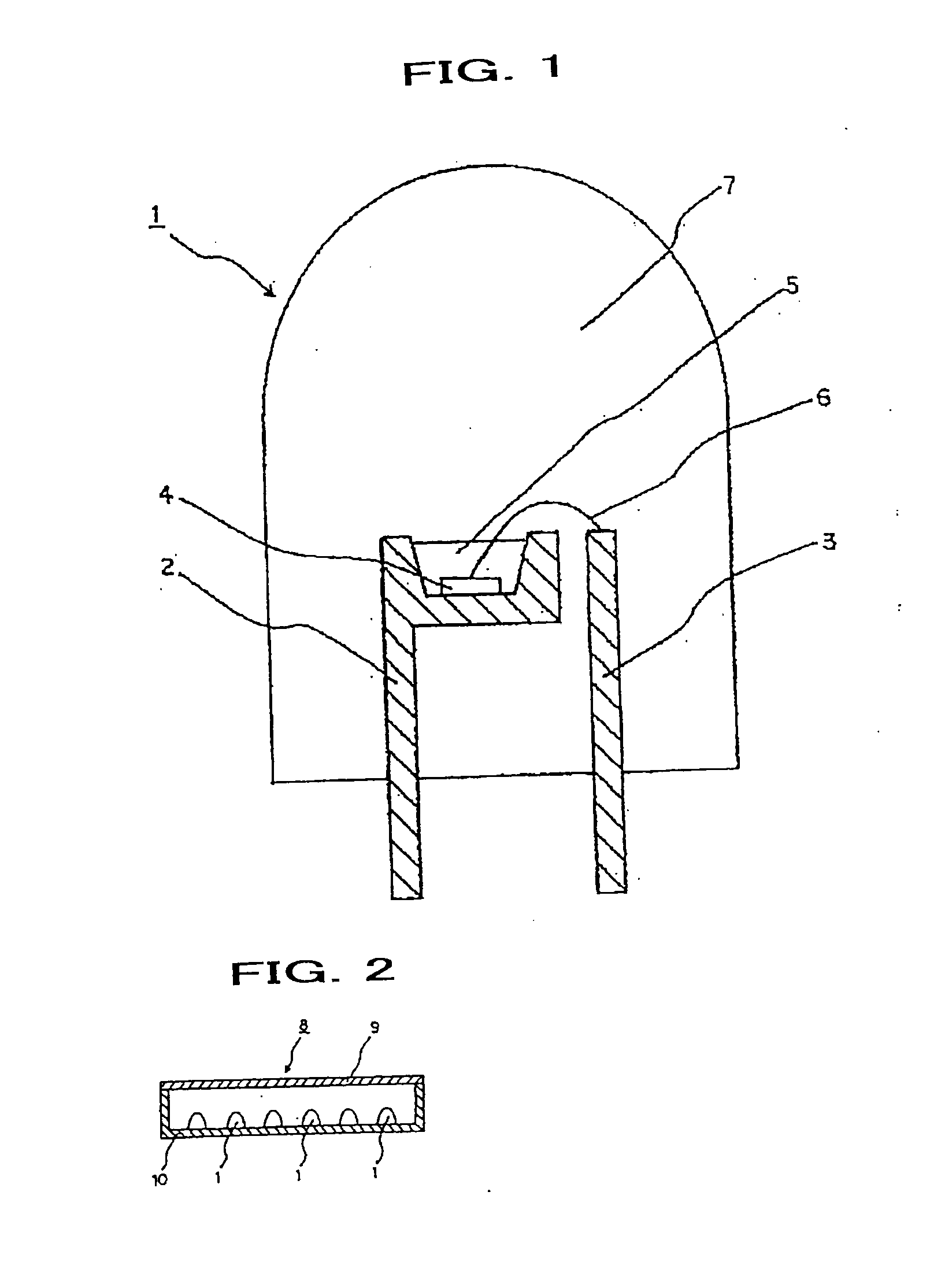
a technology of light-emitting devices and lighting systems, which is applied in the direction of discharge tubes/lamp details, luminescent compositions, discharge tubes/lamp details, etc., can solve the problems of low general color rendering index ra of light from the light-emitting devices, low luminous efficiency, and reduction of luminous flux emitted, so as to achieve excellent emission efficiency and color rendering, excellent in both luminance and color rendering

Active Publication Date: 2011-07-28
MITSUBISHI CHEM CORP
View PDF14 Cites 3 Cited by
  • Summary
  • Abstract
  • Description
  • Claims
  • Application Information

AI Technical Summary

Benefits of technology

[0010]The present invention makes possible the creation of a light emitting device which is excellent in both luminance and color rendering. The use of the light emitting device of the present invention makes possible the creation of a lighting system and a display which are excellent in both emission efficiency and color rendering.

Problems solved by technology

However, there are problems, as already pointed, that the light amount in the range of red (600 nm or longer) and blue green (480 nm to 510 nm) is small, and that the general color rendering index Ra of the light from the light emitting device is low.
This then leads to a problem of reduction in luminous flux emitted from the white LED because green light emitted from the green phosphor is absorbed by the large amount of the red phosphor, having low luminous efficiency.
Moreover, as the red phosphor used is low moisture-resistant, sulfide base red phosphor, there are problems of ease of deterioration, and of high production cost due to the difficulty in synthesis.
This leads to the problems of the white LED, which is obtained by using the red phosphor, of low durability and high production cost.
Furthermore, as the color of the emitted light from the green phosphor used is a little too yellowish, there is another problem that the shortage of blue-green range of emitted light causes inferior color rendering.
There are problems, with this LED too, of insufficient luminous flux, insufficient color rendering and vulnerability of the sulfide to deterioration when the white LED is used.[Patent Document 1] Japanese Patent Laid-Open Publication (Kokai) No. 2003-243715[Non-Patent Document 1] J. Electrochem. Soc. Vol. 150 (2003)pp.

Method used


Image

  • Light-emitting device, and lighting system, and image display using same
  • Light-emitting device, and lighting system, and image display using same

Examples


example 1

[0078]A first phosphor and a second phosphor were mixed, with weight % of 94 and 6 respectively, to create a mixture of phosphors. The first phosphor used, represented by the chemical composition of Ca3Sc2Si3O12, was a phosphor of an oxide, which has luminous efficiency of 46% and emission peak wavelength of 505 nm, and includes 0.03 mol (0.01 mol relative to 1 mol of Ca in the chemical composition) of Ce as activator agent. The second phosphor used, represented by the chemical composition of CaAlSiN3, was a phosphor of a nitride, which has luminous efficiency of 54% and emission peak wavelength of 650 nm, and includes 0.01 mol of Eu as activator agent.

[0079]This intensive emission peak observed in the emission spectrum of the first phosphor is sufficiently overlapped with wavelength of the excitation band observed in the excitation spectrum of the second phosphor. Therefore, it was confirmed that the light emitted from the first phosphor was absorbed in the second phosphor and exci...

example 2

[0085]A first phosphor with weight % of 95 and a second phosphor were mixed, to create a mixture of phosphors. The first phosphor used, represented by the chemical composition of CaSc2O4, was a phosphor of an oxide, which has luminous efficiency of 43% and emission peak wavelength of 516 nm, and includes 0.01 mol of Ce as activator agent. The second phosphor used, represented by the chemical composition of CaAlSiN3, was a phosphor of a nitride, which has luminous efficiency of 54% and emission peak wavelength of 650 nm, and includes 0.01 mol of Eu as activator agent.

[0086]This intensive emission peak observed in the emission spectrum of the first phosphor is sufficiently overlapped with wavelength of the excitation band observed in the excitation spectrum of the second phosphor. Therefore, it was confirmed that the light emitted from the first phosphor was absorbed in the second phosphor and excited the second phosphor.

[0087]Then, this mixture of phosphor was irradiated with blue li...


PUM

PropertyMeasurementUnit
emission peak wavelength L2aaaaaaaaaa
wavelengthaaaaaaaaaa

Abstract

To enhance luminance and color rendering of a light emitting device comprising phosphors as wavelength converting material andat least one semiconductor light emitting device that emits visible light, as said phosphors, are used phosphors which are one or more kinds of phosphors selected from a group consisting of oxides, oxynitrides and nitrides, and are a mixture consisting of two or more kinds of phosphors whose luminous efficiency is 35% or higher when excited by the visible light from said semiconductor light emitting device at room temperature. In addition, said mixture contains a first phosphor, and a second phosphor that is different from said first phosphor and capable of absorbing emitted light from said first phosphor, and said first phosphor is contained 85 weight % or more of said mixture of phosphors.

Description

CROSS REFERENCE TO RELATED APPLICATIONS[0001]This application is a continuation of U.S. patent application Ser. No. 11 / 631,103, filed May 8, 2007 as the U.S. National Stage of International Application No. PCT / JP05 / 011941, filed Jun. 29, 2005, the disclosures of which are incorporated herein by reference in their entireties. This application claims priority to Japanese Patent Application Number 2004-194509, filed Jun. 30, 2004, the disclosure of which is incorporated herein by reference in its entirety.TECHNICAL FIELD[0002]This invention relates to a light emitting device, and lighting system, display using the same.BACKGROUND ART[0003]Heretofore, a white-light emitting device constructed by combining a gallium nitride (GaN) base light-emitting diode (LED) as semiconductor light emitting device and phosphors as wavelength converting material has been noted as light source for a display or lighting system, making use of its advantages of low power consumption and long operating life....

Claims


Application Information

Patent Timeline
Patent Type & Authority Applications(United States)
IPC IPC(8): H01J1/62C09K11/77H01L33/50H01L33/54H01L33/56H01L33/62
CPCC09K11/0883C09K11/7734C09K11/7774H01L33/504H05B33/12H01L2224/48247H01L2224/48091C09K11/64H01L2224/45144H01L2924/00014H01L2924/00C09K11/77742C09K11/77348
Inventor SHIMOMURA, YASUOKANEDA, HIDEAKIKIJIMA, NAOTO
Owner MITSUBISHI CHEM CORP
Learn More