Software for use with deformity correction

a software and deformation technology, applied in the field of software for use with deformation correction, can solve the problems of reducing the attractiveness of using complex fixation frames, increasing the complexity of fixing devices, and increasing the difficulty of determining the optimal length and position of the struts with respect to the rings of the fixation fram

a software and deformation technology, applied in the field of software for use with deformation correction, can solve the problems of reducing the attractiveness of using complex fixation frames, increasing the complexity of fixing devices, and increasing the difficulty of determining the optimal length and position of the struts with respect to the rings of the fixation fram

US10154884B2Active Publication Date: 2018-12-18STRYKER EURO OPERATIONS HLDG LLC

Image

  • Software for use with deformity correction
  • Software for use with deformity correction
  • Software for use with deformity correction

Examples


Embodiment Construction

[0020]In one embodiment of the disclosure, software aids a user, such as a physician, surgeon, or other medical personnel, in planning and carrying out the correction of a bone deformity using a limb reconstruction frame using a web application, for example. Other software for creating a correction plan for an external fixation frame is described in U.S. Patent Publication No. 2014 / 0236153, the contents of which are hereby incorporated by reference herein.

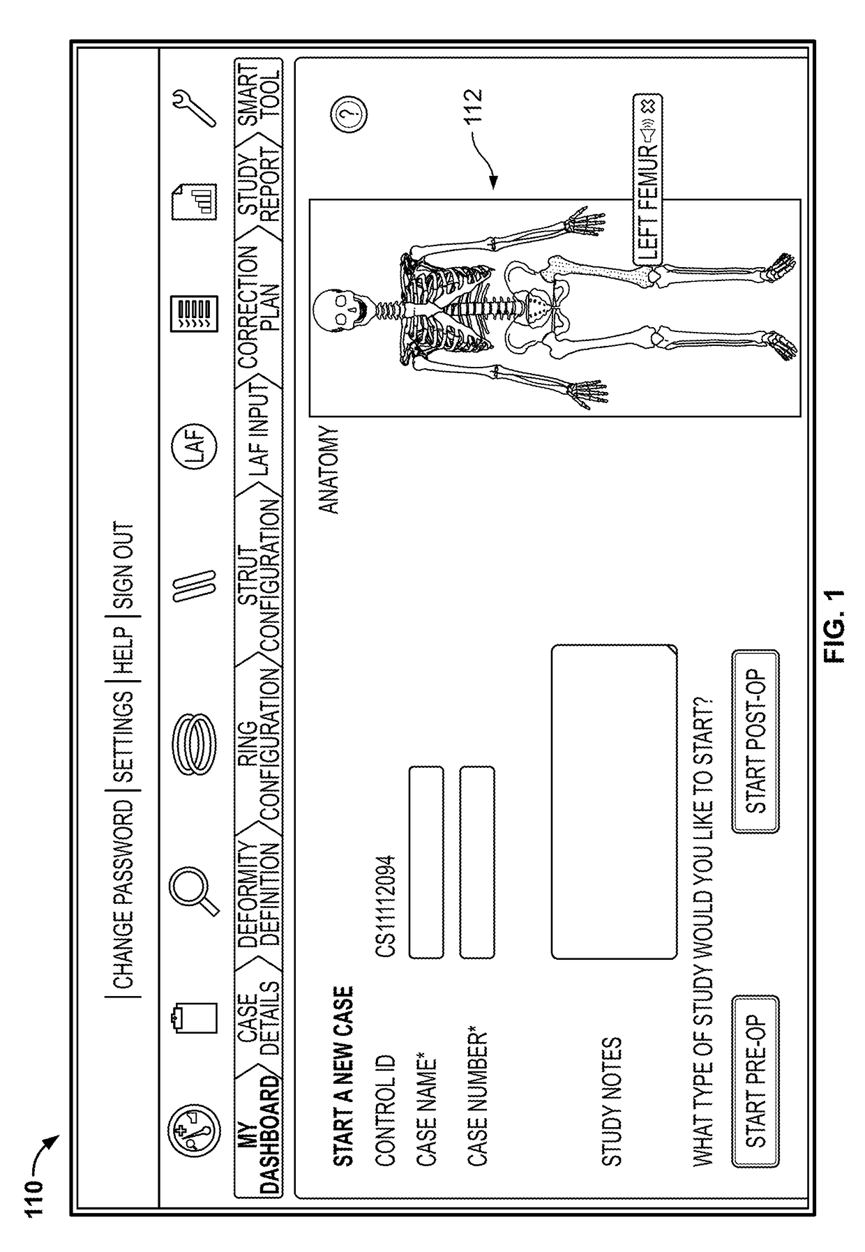
[0021]Upon starting the application, the user is presented with a login screen. The login screen preferably includes a username field and password field in which the user enters, respectively, a username and password to gain further access to the application. This step of authentication may, for example, help maintain compliance with patient privacy regulations. In cases where a first time user tries to gain further access to the application, a new user account may have to be created.

[0022]As shown in FIG. 1, upon logging in, the u...


PUM


Abstract

A method of generating a correction plan for correcting a deformed bone includes inputting to a computer system a first image of the deformed bone in a first plane and inputting to the computer system a second image of the deformed bone in a second plane. Image processing techniques are employed to identify a plurality of anatomical landmarks of the deformed bone in the first image. The first image of the deformed bone is displayed on a display device. A graphical of the deformed bone is autonomously generated and graphically overlaid on the first image of the deformed bone on the display device, the graphical template including a plurality of lines, each line connected at each end to a landmark point corresponding to one of the anatomical landmarks. A model of the deformed bone may be autonomously generated based on the graphical template.

Description

CROSS-REFERENCE TO RELATED APPLICATIONS[0001]This application is a continuation of U.S. patent application Ser. No. 15 / 171,121, filed Jun. 2, 2016, the disclosure of which is hereby incorporated by reference herein.FIELD OF THE INVENTION[0002]The present disclosure relates to software used in planning the correction of bone deformities preoperatively and / or postoperatively, and in particular relates to autonomously or semi-autonomously creating virtual models to create the correction plan.BACKGROUND OF THE INVENTION[0003]Currently, external fixation systems may be used to correct skeletal deformities using the distraction osteogenesis process, for example. The Ilizarov external fixation device (or similar system) may be used for such a purpose. The Ilizarov-type devices generally translate bone segments by manipulating the position of rings connected to each bone segment.[0004]These external fixation devices generally utilize threaded rods fixated to through-holes in the rings to bu...

Claims


Application Information

Patent Timeline
18 Dec 2018
Publication
US10154884B2
IPC
G06K9/00; A61B34/00; A61B34/10; A61B90/00; A61B17/62
CPC
A61B34/10; A61B34/25; A61B17/62; A61B2090/376; A61B2034/105; A61B2034/107; A61B2034/108; A61B2034/104
Inventors
KUMAR, ANUP; ANJANAPPA, SRIDHAR