Portable rail system for mounting an engraving device

a technology of engraving device and rail system, which is applied in the field of engraving system, can solve the problem that the system does not address all situations

Active Publication Date: 2018-12-25
REDART TECH LLC
View PDF17 Cites 2 Cited by
  • Summary
  • Abstract
  • Description
  • Claims
  • Application Information

AI Technical Summary

Problems solved by technology

While conventional CNC routing systems are useful where the hardened material or workpiece can be brought to a shop for engraving, such systems do not address all situations in which a hardened surface is required to be engraved.

Method used


Image

  • Portable rail system for mounting an engraving device
  • Portable rail system for mounting an engraving device
  • Portable rail system for mounting an engraving device

Examples


Embodiment Construction

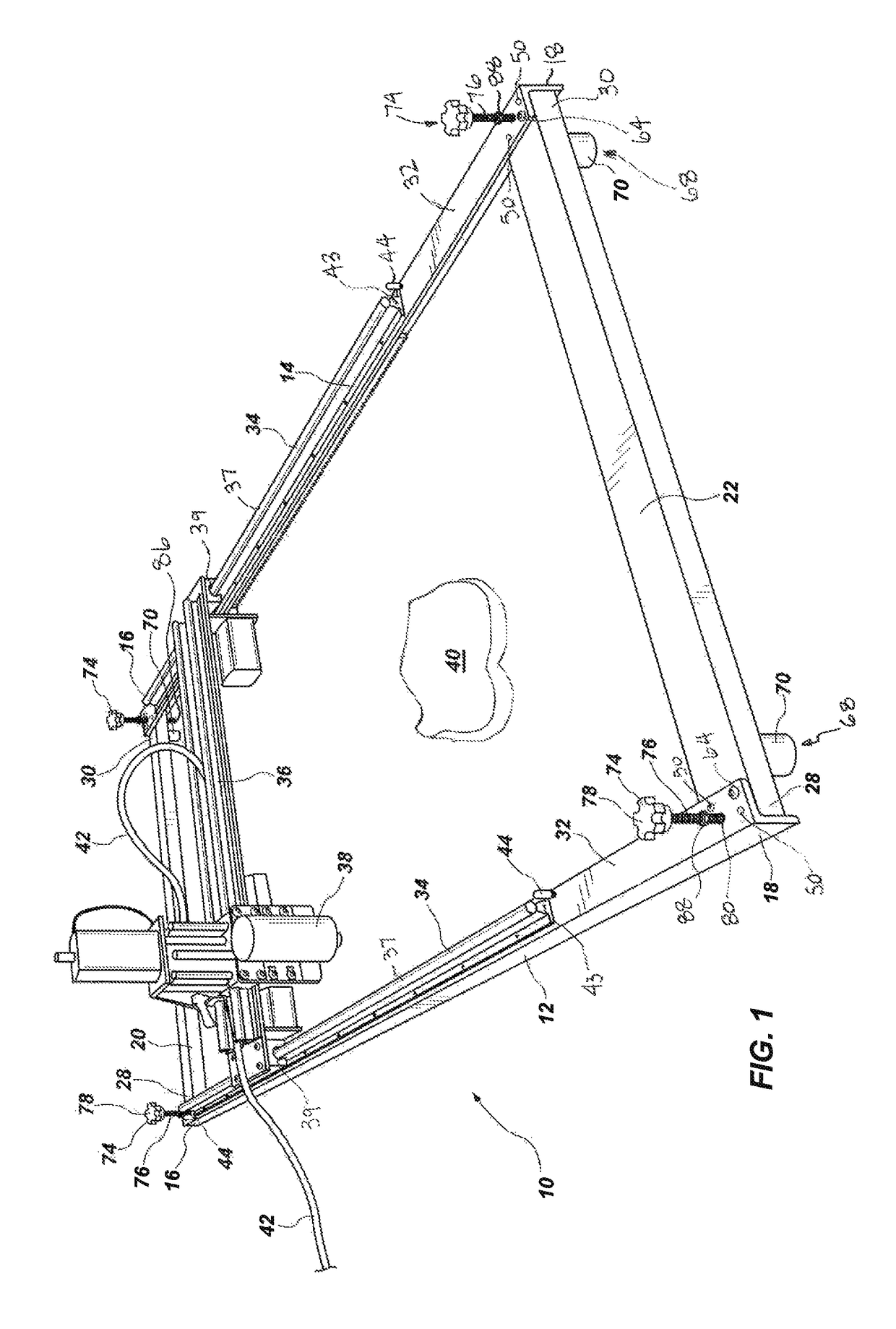
[0034]FIG. 1 shows a view of a portable rail system 10, or frame 10, in accordance with the present disclosure. The portable rail system 10 comprises two rail lengths 12, 14, each rail length 12, 14 having a first end 16 and a second end 18. The portable rail system 10 further comprises at least two crossbars 20, 22 which, in use, are positioned to each extend between the two rail lengths 12, 14 to position the two rail lengths 12, 14 in parallel spaced apart arrangement relative to each other. While two crossbars 20, 22 are shown, more crossbars may be employed. Each crossbar has a first end 28 and a second end 30 which align with and are, in use, secured to the first end 16 and second end 18, respectively, of the corresponding two rail lengths 12, 14, as shown. Specifically, the first end 28 of each crossbar 20, 22 is engaged with the first rail length 12 and the second end 30 of each crossbar 20, 22 is engaged with the second rail length 14. The crossbars, 20, 22 are, in use, spa...


PUM

PropertyMeasurementUnit
lengthaaaaaaaaaa
lengthsaaaaaaaaaa
heightaaaaaaaaaa

Abstract

A portable rail system for mounting an engraving device includes rails and crossbar members that are precisely joined, and include height adjustment devices for incrementally adjusting the height of the rail system relative to a work surface or contact surface, thus making the portable rail system capable of being assembled and disassembled at a work site to enable the use of an engraving device, such as a CNC router engraving systems, in situ, or on-site, rather than in a workshop. The portable rail system enables the use of a CNC router device or other engraving device on vertical surfaces.

Description

TECHNICAL FIELD[0001]This disclosure relates in general to engraving systems that are used to engrave hard materials, and, in particular, to a portable rail or frame system for mounting an engraving device thereto for use in engraving hard materials in situ.BACKGROUND OF THE DISCLOSURE[0002]Engraving systems for use in engraving hard materials, such as stone, wood, hardened plastics, etc., are known. Such systems are commonly referred to as CNC (computer numerical control) router systems and generally comprise a CNC router that is secured to a gantry which slidingly moves along a supporting framework that is elevated above a horizontal work surface. The conventional form of such assemblies comprises a work table having a horizontal flat surface on which is placed a sheet or slab of hardened material. The supporting framework is positioned in elevation above the workpiece and supports a slidable gantry to which the CNC router is connected.[0003]While conventional CNC routing systems ...

Claims


Application Information

Patent Timeline
Patent Type & Authority Patents(United States)
IPC IPC(8): B23Q9/00B44B3/06B44B1/06B44B3/00B23Q1/62B44B3/02B23Q1/01B23C1/20B24B23/08
CPCB23Q9/0042B23Q1/012B23Q1/621B44B1/06B44B3/006B44B3/02B44B3/06B44B3/009Y10T409/306384B23C1/20B24B23/08
Inventor ASHWORTH, HENRY
Owner REDART TECH LLC
Why Eureka
Try Eureka