

Boost chopper circuit
a technology of chopper and circuit, applied in the direction of power conversion system, dc-dc conversion, instruments, etc., can solve the problem of short circuit of the failure device of the switching device circuit, and achieve the effect of significant reducing or preventing the failure of a capacitor and reducing or preventing the application
- Summary
- Abstract
- Description
- Claims
- Application Information
AI Technical Summary
Benefits of technology
Problems solved by technology
Method used
Image

Examples
first embodiment
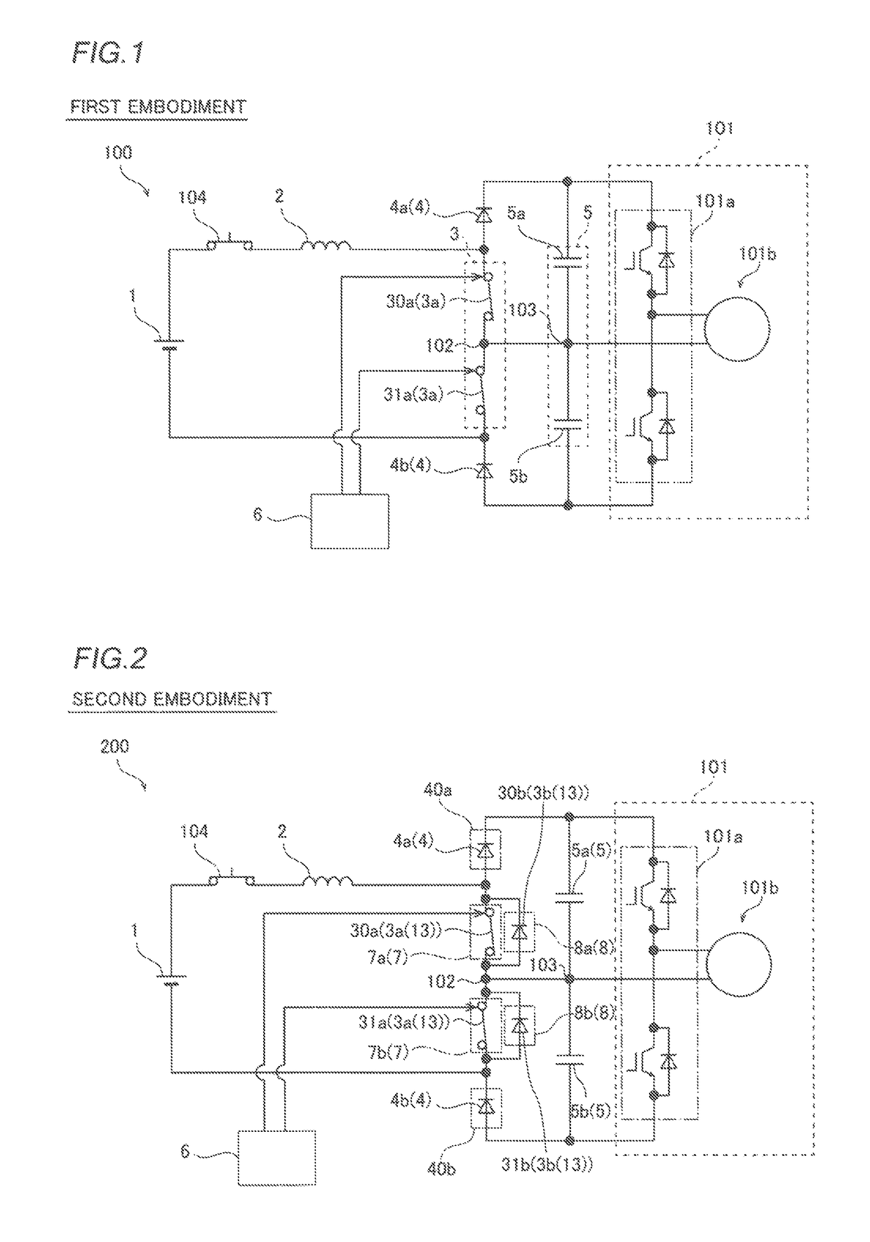
[0030]The structure of a boost chopper circuit 100 according to a first embodiment of the present invention is now described with reference to FIG. 1.
[0031](Structure of Boost Chopper Circuit)
[0032]As shown in FIG. 1, the boost chopper circuit 100 is configured to boost a voltage output from a direct-current output circuit 1 and supply the boosted voltage to a loading device 101. According to the first embodiment, the boost chopper circuit 100 is configured as a so-called three-level boost chopper circuit. The direct-current output circuit 1 is configured as a direct-current power supply, or includes an alternating-current power supply and a rectifier circuit and is configured to be capable of outputting a direct current having a rectification waveform obtained by rectifying an alternate current.
[0033]The boost chopper circuit 100 includes a reactor 2, a switching device circuit 3, a backflow prevention diode circuit 4, a capacitor circuit 5, and a control circuit 6. In general, the...
second embodiment
[0062]The structure of a boost chopper circuit 200 according to a second embodiment is now described with reference to FIG. 2. According to the second embodiment, the boost chopper circuit 200 is configured as a three-level boost chopper circuit similarly to the first embodiment. On the other hand, according to the second embodiment, the boost chopper circuit 200 includes an antiparallel diode element 3b connected in anti-parallel to a first switching device 3a. Portions of the boost chopper circuit 200 similar to those of the boost chopper circuit 100 according to the aforementioned first embodiment are denoted by the same reference numerals, to omit the description.
[0063](Structure of Boost Chopper Circuit)
[0064]According to the second embodiment, a switching device circuit 13 includes the antiparallel diode element 3b connected in anti-parallel to the first switching device 3a. Specifically, the antiparallel diode element 3b includes a first antiparallel diode 30b connected in an...
third embodiment
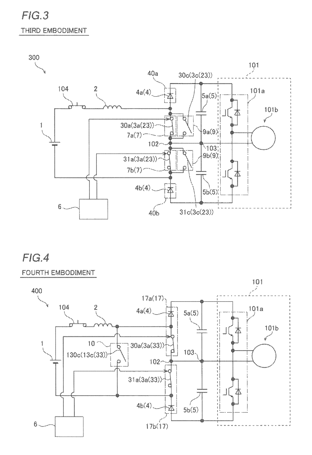
[0078]The structure of a boost chopper circuit 300 according to a third embodiment is now described with reference to FIG. 3. According to the third embodiment, the boost chopper circuit 300 is configured as a three-level boost chopper circuit similarly to the first embodiment and the second embodiment. On the other hand, according to the third embodiment, the boost chopper circuit 300 includes a second switching device 3c connected in parallel to a first switching device 3a unlike the second embodiment in which the boost chopper circuit 200 includes the antiparallel diode element 3b connected in anti-parallel to the first switching device 3a. Portions of the boost chopper circuit 300 similar to those of the boost chopper circuit 200 according to the aforementioned second embodiment are denoted by the same reference numerals, to omit the description.
[0079](Structure of Boost Chopper Circuit)
[0080]According to the third embodiment, a switching device circuit 23 includes the first swi...
PUM
 Abstract
Description
Claims
Application Information