
Prevention of gas accumulation above ESP intake with inverted shroud

a technology of inverted shroud and gas accumulation, which is applied in the direction of survey, construction, and well accessories, etc., can solve the problems of cable splicing or motor lead extension, failure of packer penetration, and restricted use of tubing casing annulus

Active Publication Date: 2019-08-13
SAUDI ARABIAN OIL CO
View PDF12 Cites 9 Cited by
  • Summary
  • Abstract
  • Description
  • Claims
  • Application Information

AI Technical Summary

Benefits of technology

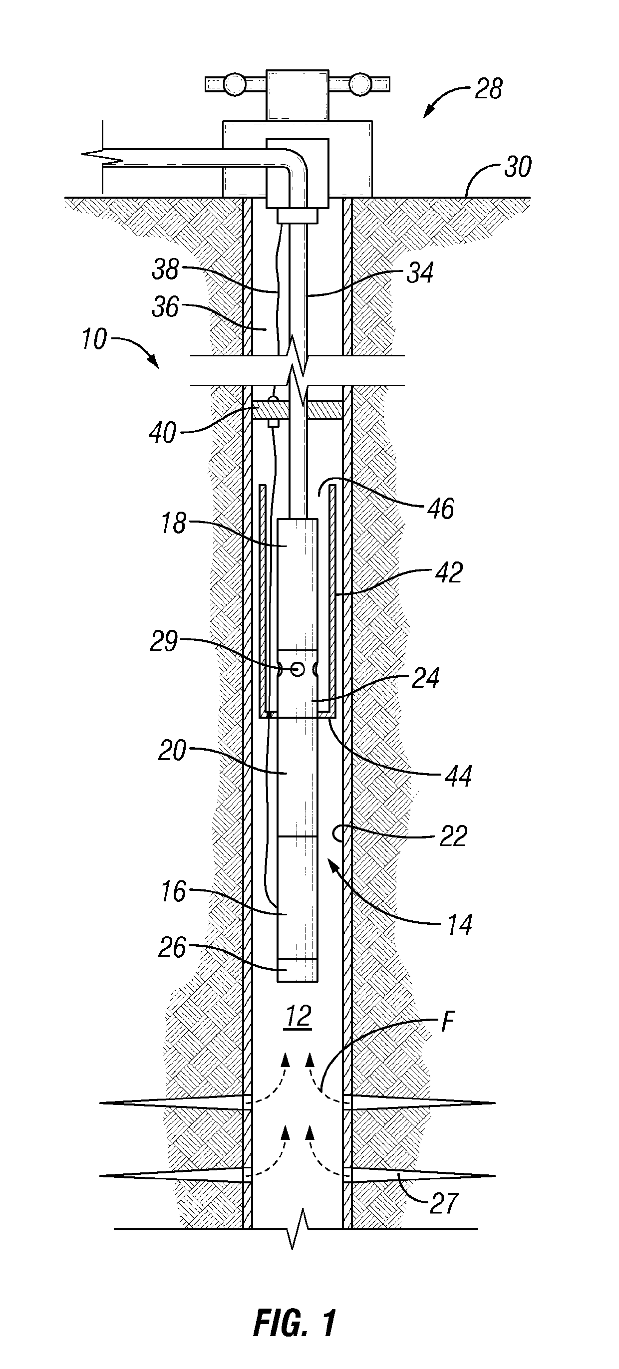
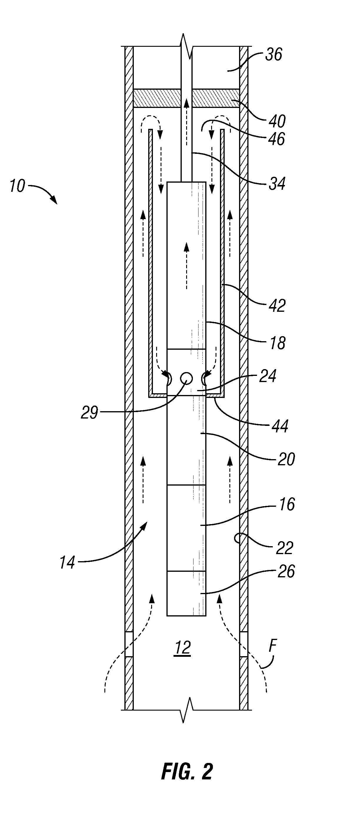
The patent text describes systems and methods for using an inverted shroud to keep gas moving with well fluids. This configuration reduces or eliminates pump gas lock and prevents electrical failures related to corrosive gas attacks on cables and connectors. The motor can be located downstream of perforations through an outer tubular member. The open end of the inverted shroud can be spaced from the packer assembly a distance to allow mixing of the gas and liquid well fluids. The bottom of the packer assembly can be free of accumulated gas. These technical effects result in improved performance and reliability of electrical submersible pump assemblies.

Problems solved by technology

In addition, some regulations may restrict the use of the tubing casing annulus for the delivery of production fluids to the surface.
However, the accumulation of gas below the packer can be detrimental to the electrical connectors, for example with corrosive gases such as H2S.
The exposure to these gases often results in failures at the packer penetrator, cable splices or the motor lead extension that are located at the packer.
If the gas completely fills the impeller passages, the pump can become gas locked and fail.
However, such systems require new specialized components such as a pod, shroud hanger, stinger, and others, that need to be incorporated into the equipment assembly.
These additional specialized components increase the overall cost of the assembly.
This additional pressure loss can trigger additional gas breakout within the pod system.

Method used


Image

  • Prevention of gas accumulation above ESP intake with inverted shroud
  • Prevention of gas accumulation above ESP intake with inverted shroud

Examples


Embodiment Construction

[0017]Embodiments of the present disclosure will now be described more fully hereinafter with reference to the accompanying drawings which illustrate embodiments of the disclosure. Systems and methods of this disclosure may, however, be embodied in many different forms and should not be construed as limited to the illustrated embodiments set forth herein. Rather, these embodiments are provided so that this disclosure will be thorough and complete, and will fully convey the scope of the disclosure to those skilled in the art. Like numbers refer to like elements throughout, and the prime notation, if used, indicates similar elements in alternative embodiments or positions.

[0018]In the following discussion, numerous specific details are set forth to provide a thorough understanding of the present disclosure. However, it will be obvious to those skilled in the art that embodiments of the present disclosure can be practiced without such specific details. Additionally, for the most part, ...


PUM


Abstract

A system for producing hydrocarbons from a subterranean well includes an electrical submersible pump assembly with a pump, intake, protector, and motor. A production tubing is in fluid communication with the electrical submersible pump assembly and has an inner bore sized to deliver well fluids containing both gases and liquids from the electrical submersible pump assembly to a wellhead assembly. A packer assembly circumscribes the production tubing downstream of the electrical submersible pump assembly. An inverted shroud has a closed end located between the intake and the protector and an opposite open end that is open towards the packer assembly.

Description

BACKGROUND OF THE DISCLOSURE1. Field of the Disclosure[0001]The disclosure relates generally to electrical submersible pumps and in particular, to electrical submersible pump assemblies that reduce gas accumulation above fluid intakes.2. Description of the Related Art[0002]One method of producing hydrocarbon fluid from a well bore that lacks sufficient internal pressure for natural production is to utilize an artificial lift method such as an electrical submersible pump (ESP). A string of tubing or pipe known as a production string suspends the submersible pumping device near the bottom of the well bore proximate to the producing formation. The submersible pumping device is operable to retrieve production zone fluid, impart a higher pressure to the fluid and discharge the pressurized production zone fluid into production tubing. Pressurized well bore fluid rises towards the surface motivated by difference in pressure. Electrical submersible pumps can be useful, for example, in high ...

Claims


Application Information

Patent Timeline
Patent Type & Authority Patents(United States)
IPC IPC(8): E21B43/12E21B47/00E21B33/12E21B47/06
CPCE21B43/128E21B33/12E21B47/0007E21B47/065E21B47/06E21B47/008E21B47/07
Inventor EJIM, CHIDIRIM ENOCHXIAO, JINJIANGLASTRA, RAFAEL ADOLFO
Owner SAUDI ARABIAN OIL CO
Learn More