Method of measurement of multilayer structures

a multi-layer structure and measurement method technology, applied in the direction of instruments, optical elements, active medium materials, etc., can solve the problems of destroying the measurement procedure used in zobel '417, tedious, and one material at a time, and none of the above methods can both non-destructively determine the number of layers in the multi-layer structur

Active Publication Date: 2019-01-29
LUMETRICS
View PDF10 Cites 6 Cited by
  • Summary
  • Abstract
  • Description
  • Claims
  • Application Information

AI Technical Summary

Problems solved by technology

However, the measurement procedure used in Zobel '417 is destructive since it requires the sample to be shattered into small grains and immersing it in the index matching liquids.
It also can only measure one material at a time and is tedious.
None of the above methods can both non-destructively determine the number of layers in a multilayer structure and identify the material used in each of the layers of the multilayer structure in the correct physical order of the materials in the structure.
The disclosure of these patents and published patent applications notwithstanding, there remains an unmet need to be able to identify the material that each of the layers in a multilayer structure is composed of non-destructively.

Method used


Image

  • Method of measurement of multilayer structures
  • Method of measurement of multilayer structures
  • Method of measurement of multilayer structures

Examples


first embodiment

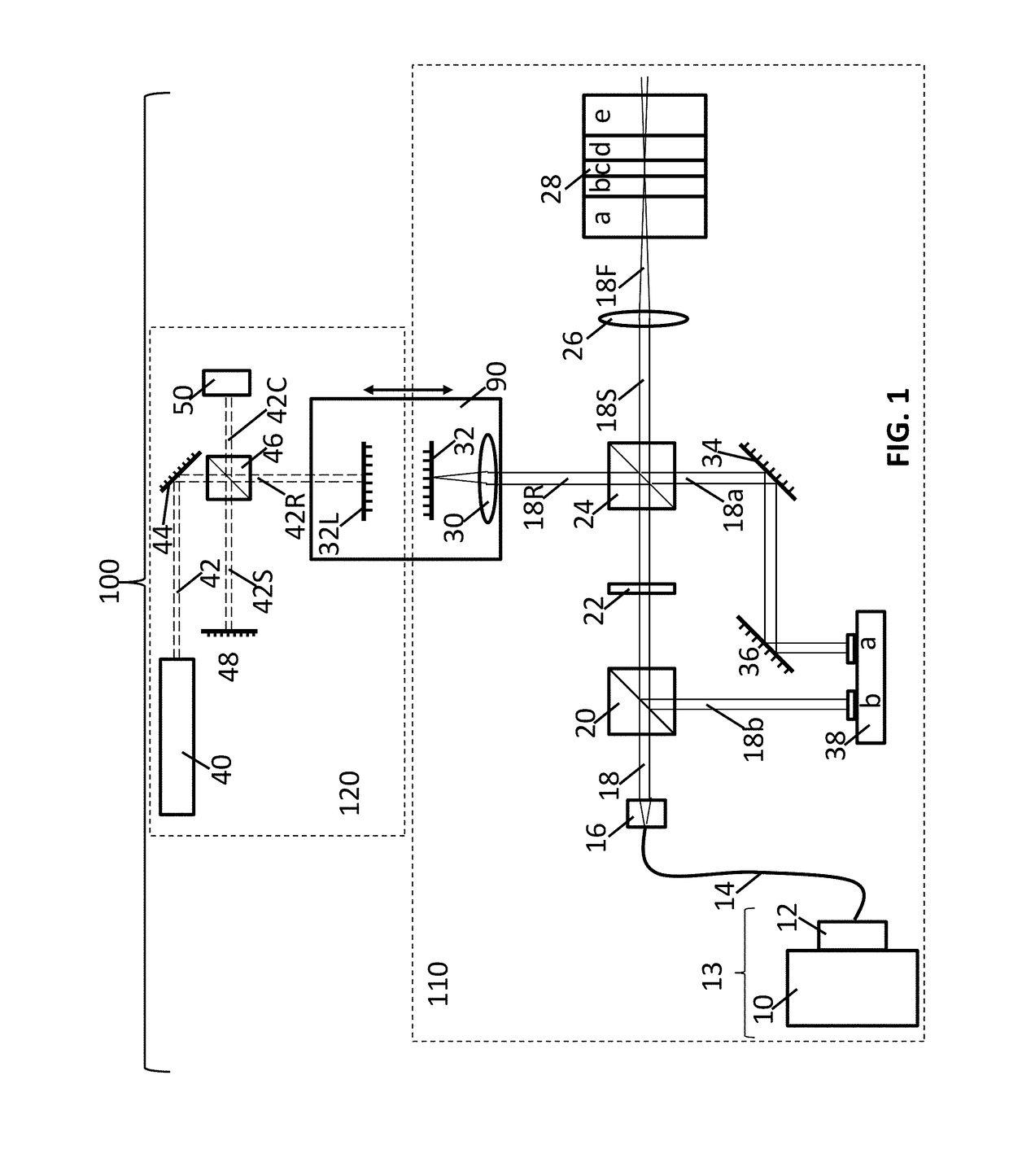
[0033]Turning now to FIG. 1, a schematic of an interferometer apparatus 100 used to measure the optical thickness of each of the layers in a multilayer structure 28 as a function of wavelength is shown. The interferometer apparatus 100 is a dual interferometer comprising a free-space low-coherence interferometer 110 (shown in the lower dashed rectangle) and a laser interferometer 120 (shown in the upper dashed rectangle). The two interferometers share a common variable optical path delay element 90 as described in Marcus '409. The laser interferometer 120 continuously measures the displacement of the reference path and is used to provide an accurate distance scale for the low-coherence interferometer as described in Marcus '409.

[0034]As shown in FIG. 1, the light source of the free space low-coherence interferometer 110 is a broadband low-coherence light source 10, and preferably a supercontinuum light source such as an NKT Photonics EXW-12 Supercontinuum light source (SCLS) which e...

second embodiment

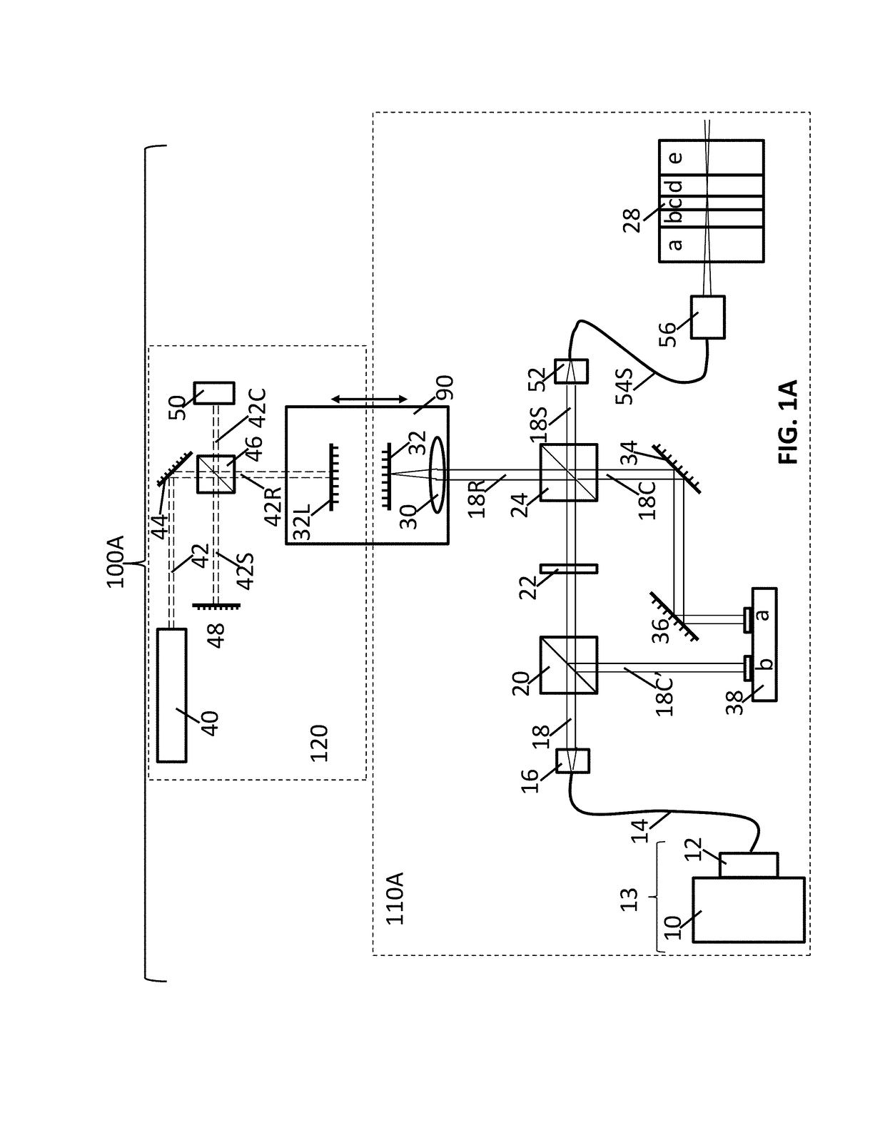
[0038]FIG. 1A shows a schematic of an interferometer apparatus 100A used to measure the optical thickness of each of the layers in a multilayer structure 28 as a function of wavelength. Most of the components of interferometer apparatus 100 and 100A are the same, and all components of the laser interferometer 120 are the same in both embodiments. The only differences in the components between low-coherence interferometer 110A and low-coherence interferometer 110 occur in the sample arm of the low-coherence interferometer 110A. The focusing lens 26 is replaced with a fiber collimator 52 which is used to couple the incident light portion of sample arm collimated beam 18S into a sample arm optical fiber 54S which is then input into an optical probe 56 which focuses light onto the multilayer structure 28. Part of the light that is focused on the multilayer structure 28 through optical probe 56 reflects off each optical interface of the multilayer structure 28 back through optical probe ...

third embodiment

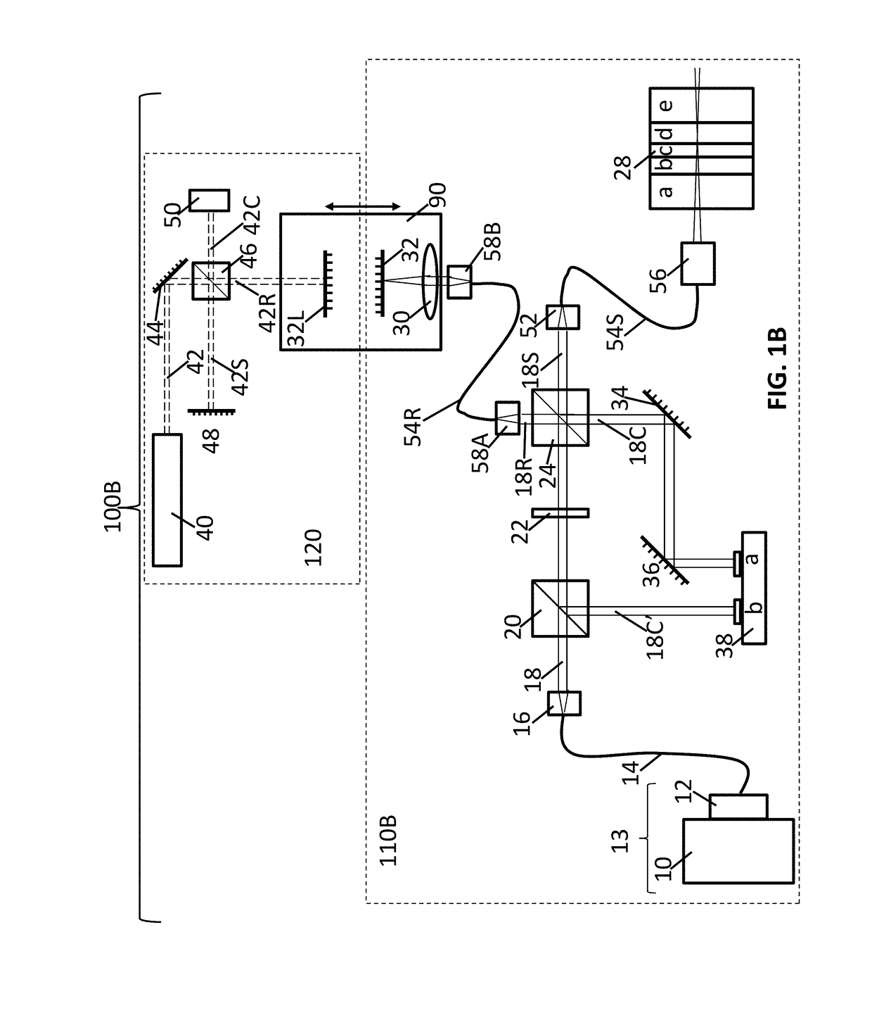
[0039]FIG. 1B shows a dual interferometer apparatus 100B used to measure the optical thickness of each of the layers in a multilayer structure 28 as a function of wavelength. Most of the components of dual interferometer apparatus 100A and 100B are the same, and all components of the laser interferometer 120 are the same in both embodiments. The only differences in the components between low-coherence interferometer 110A and low-coherence interferometer 110B occur in the reference arm of the low-coherence interferometer 110B. Instead of the incident light portion of reference arm collimated beam 18R being directly incident on the reference arm lens 30 as shown in FIG. 1 and FIG. 1A, the incident light portion of reference arm collimated beam 18R shown in FIG. 1B part of the collimated beam 18R region is coupled into a fiber collimator 58A and transmitted through optical fiber 54R and coupled into a second fiber collimator 58B before being incident on reference arm lens 30 which then...


PUM

PropertyMeasurementUnit
wavelength rangeaaaaaaaaaa
coherence lengthaaaaaaaaaa

Abstract

A method of identifying the material and determining the physical thickness of each layer in a multilayer structure is disclosed. The method includes measuring the optical thickness of each of the layers of the multilayer object as a function of wavelength of a light source and calculating a normalized group index of refraction dispersion curve for each layer in the multilayer structure. The measured normalized group index of refraction dispersion curves for each of the layers is then compared to a reference data base of known materials and the material of each layer is identified. The physical thickness of each layer is then determined from the group index of refraction dispersion curve for the material in each layer and the measured optical thickness data. A method for determining the group index of refraction dispersion curve of a known material is also disclosed.

Description

BACKGROUNDTechnical Field[0001]The present invention relates to the non-destructive characterization of multilayer structures including determination of the number of layers, identification of the materials comprising each layer and the thickness of each layer in the multilayer structure.Description of Related Art[0002]Non-destructive product verification testing is important in many industries and is extremely important for multilayer structures used for a variety of commercial and military applications. Being able to identify the number of layers as well as the material that each layer is composed of in multilayer structures along with the thickness of each of the layers is becoming more and more important for product verification testing and is also useful in reverse engineering. It is extremely important to verify that the multilayer structures meet specifications in fields including automotive, aerospace and building glazing, transparent armor, compound lenses, semiconductors, ...

Claims


Application Information

Patent Timeline
Patent Type & Authority Patents(United States)
IPC IPC(8): G01B11/06H01S3/00G02B27/30G02B27/12G01N21/45G01B9/02H01S3/22
CPCG01N21/45G01B9/02002G01B11/06G01N2201/06113H01S3/2222G02B27/30H01S3/005H01S3/0071G02B27/126G01B9/02028G01B11/0625G01B11/0675G01N2021/8438
Inventor MARCUS, MICHAEL A.GIBSON, DONALD S.HADCOCK, KYLE J.IGNATOVICH, FILIPP V.
Owner LUMETRICS
Why Eureka
Try Eureka