Method of generating a geodetic reference database product

a geodetic reference and database technology, applied in the field of geodetic reference database products, can solve the problems of not being able to align 3d models and sensed images, and achieve the effects of improving the process of rectifying aerial or satellite images, and reducing the difficulty of obtaining dsms

Active Publication Date: 2015-02-17
TOMTOM GLOBAL CONTENT
View PDF18 Cites 110 Cited by
  • Summary
  • Abstract
  • Description
  • Claims
  • Application Information

AI Technical Summary

Benefits of technology

[0039]Mobile mapping vehicles capture mobile mapping data captured by means of digital cameras, range sensors, such as laser / radar sensors, and position determination means including GPS and IMU mounted to a vehicle driving across the road based earth surface, the mobile mapping data comprising simultaneously captured image data, laser / radar data and associated position data in a geographic coordinate system. Position determining means enables us to determine the position with a horizontal absolute accuracy of 50 cm and a vertical accuracy of 1.5 m. By means of the laser / radar sensor in combination with the determined associated position data, it is possible to create a surface model with a relative horizontal accuracy of 50 cm for 100 m and a relative vertical accuracy of 35 cm for 100 m. With better hardware, i.e. faster range sensor providing a denser laser cloud an accuracy of 1 cm is achievable.
[0061]using the position of the 3D-models in the coordinate reference system to rectify the aerial or satellite image. As 3D-models of, for example, road segments describe the earth surface in more detail and larger extend than a set of ground control points, they enable us to improve the rectification process. The method could also be used to validate orthorectified aerial or satellite images and rectify, i.e. correct, image parts that match but have different coordinates in the coordinate reference system.

Problems solved by technology

Therefore, it is not possible to align the 3D models and the sensed images.

Method used


Image

  • Method of generating a geodetic reference database product
  • Method of generating a geodetic reference database product
  • Method of generating a geodetic reference database product

Examples


Embodiment Construction

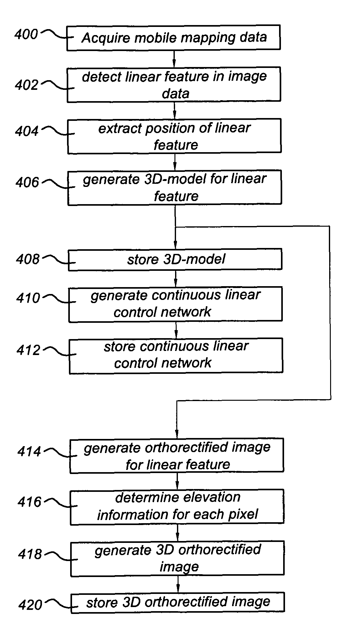
[0075]FIG. 4 shows a simplified flow diagram of the method according to the invention. The method starts with action 400, by acquiring mobile mapping data. Mobile mapping data is captured by means of digital cameras, laser sensors, for example a laser scanner, and position determination means including GPS and IMU mounted to a vehicle driving across the earth surface, the mobile mapping data comprising simultaneously captured image data, laser data and associated position data in a geographic coordinate system. A vehicle provided with position determination means, laser sensors and digital cameras for collecting mobile mapping data is called a mobile mapping system MMS. A position determination means is at least arranged to determine the position of the vehicle in a coordinate reference system and optionally with the orientation of the vehicle. It should be noted that in stead of laser sensors any other range sensor, such as a LADAR, LIDAR and RADAR, could be used to capture data th...


PUM


Abstract

A method of generating a geodetic reference database product is disclosed The method comprises acquiring mobile mapping data captured by means of digital cameras, range sensors and position determination means including GPS and IMU mounted to a vehicle driving across the earth surface, the mobile mapping data comprising simultaneously captured image data, range data and associated position data in a geographic coordinate system. Linear stationary earth surface features are derived from the mobile mapping data by processing the image data, range data and associated position data. 3D-models are generated for the linear stationary earth surface features in the geographic coordinate system from the image data, range data and associated position data and stored in a database to obtain the geodetic reference database product. A 3D-model could include an image representing the colors of the surface of the 3D model or a set of smaller images representing photo-identifiable objects along the model. The 3D-models could be used to rectify aerial imagery, to correct digital elevation models and to improve the triangulation of digital elevation models.

Description

[0001]This application is the National Stage of International Application No. PCT / US2008 / 013502, filed Dec. 9, 2008 and designating the United States. The entire contents of this application is incorporated herein by reference.FIELD OF THE INVENTION[0002]The present invention relates to the field of generating a geodetic reference database product.[0003]The invention further relates to a computer implemented system for generating a geodetic reference database product, a geodetic reference database product, a computer program product and a processor readable medium provided with the computer program product or the geodetic reference database product. A geodetic reference database product can be useful when orthorectifying different images of the same geographic areaBACKGROUND OF THE INVENTION[0004]Ground control points (GCP's) are used in orthorectifying satellite, aerial or aero survey imagery to standard map projections. A ground control point can be any point on the surface of the...

Claims


Application Information

Patent Timeline
Patent Type & Authority Patents(United States)
IPC IPC(8): G01C21/28G01C11/04G01S13/89G01S17/89G06F17/30
CPCG06F17/30241G01S17/89G01S13/89G01C11/04G06F16/29
Inventor MIKSA, KRZYSZTOFCLARK, JAYHAGAN, JAMES EDWARD
Owner TOMTOM GLOBAL CONTENT
Why Eureka
Try Eureka