

Folding propeller
a technology for folding propellers and boats, applied in the direction of rotary propellers, propellers with rotating parts, etc., can solve the problems of affecting the effectiveness of propellers, affecting the performance of propellers, and affecting the efficiency of propellers, so as to achieve low tensile strength, low moment of inertia, and corrosion resistance.
- Summary
- Abstract
- Description
- Claims
- Application Information
AI Technical Summary
Benefits of technology
Problems solved by technology
Method used
Image

Examples
Embodiment Construction
[0043]In the following text, the figures will be described one by one and the different parts and positions seen in the figures will be numbered with the same numbers in the different figures. Not all parts and positions indicated in a specific figure will necessarily be discussed together with that figure.
DETAILED DESCRIPTION OF THE INVENTION
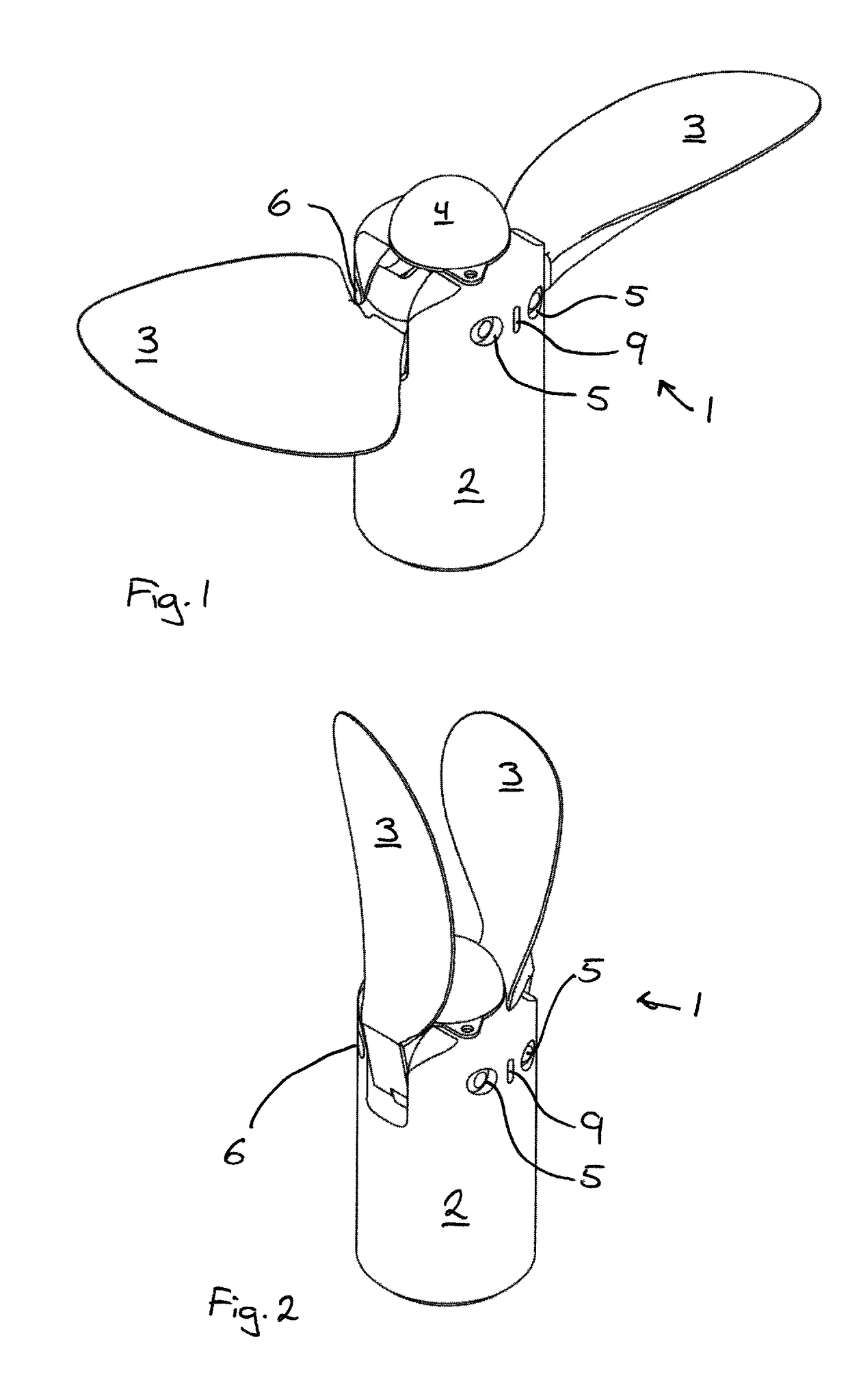
[0044]In FIG. 1 a two bladed folding propeller 1 is seen in an operative position, where the blades 3 are unfolded and extending in a more or less radial direction from the hub 2. At the end of the hub 2 an anode 4 is seen and on the side of the hub 2 the first set of holes 5 in the hub 2 is seen. In said first set of holes 5 the pivot pins 7 are arranged and secured.
[0045]FIG. 2 show the same folding propeller 1 as seen in FIG. 1, but here, in an inoperative position, with the blades 3 folded and pointing in an axial direction.
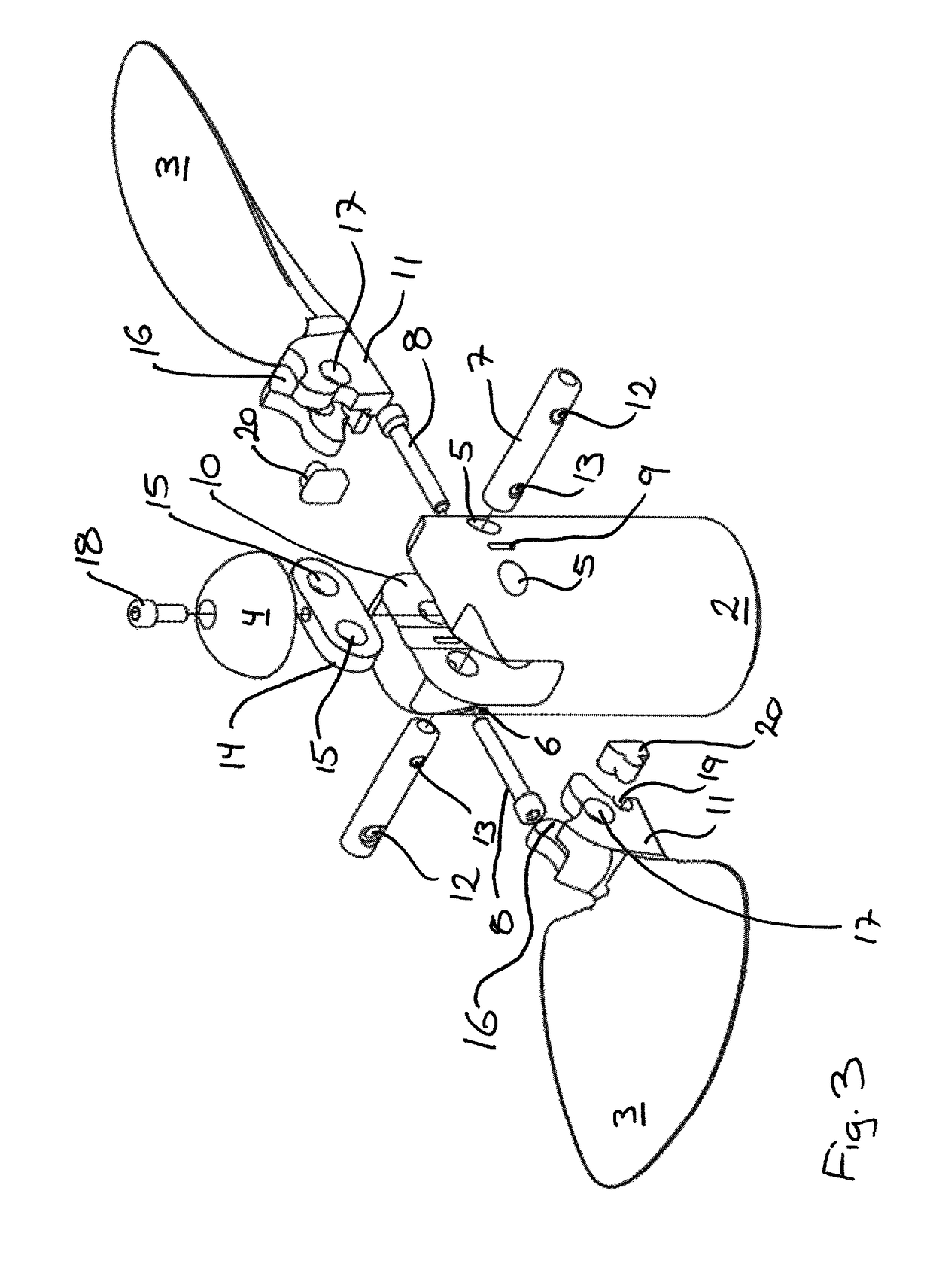
[0046]In FIG. 3 the same two bladed folding propellers 1, as also seen in the preceding figures, are seen, but here in...
PUM
 Abstract
Description
Claims
Application Information