Swivel

a technology of swivel and screw, which is applied in the field of swivel, can solve the problems that the locking screw b>63/b> might not be able to sustain the weight of the heavy duty object, and the swivel b>60/b> is prone to detach from the heavy duty obj

Inactive Publication Date: 2019-03-05
LIN SHU CHAN
View PDF24 Cites 3 Cited by
  • Summary
  • Abstract
  • Description
  • Claims
  • Application Information

AI Technical Summary

Benefits of technology

[0007]The main objective of the present invention is to pro

Problems solved by technology

Once the conventional swivel 60 is utilized to connect a heavy duty object, the locking screw 63 might not be able to su

Method used


Image

  • Swivel
  • Swivel
  • Swivel

Examples


Embodiment Construction

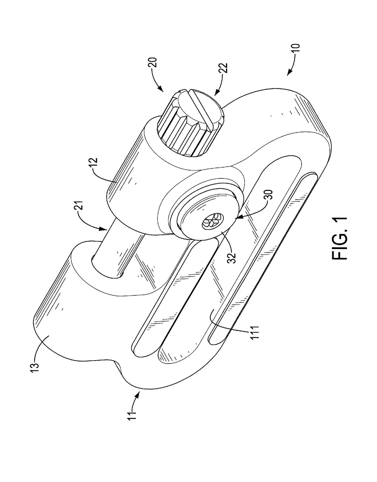
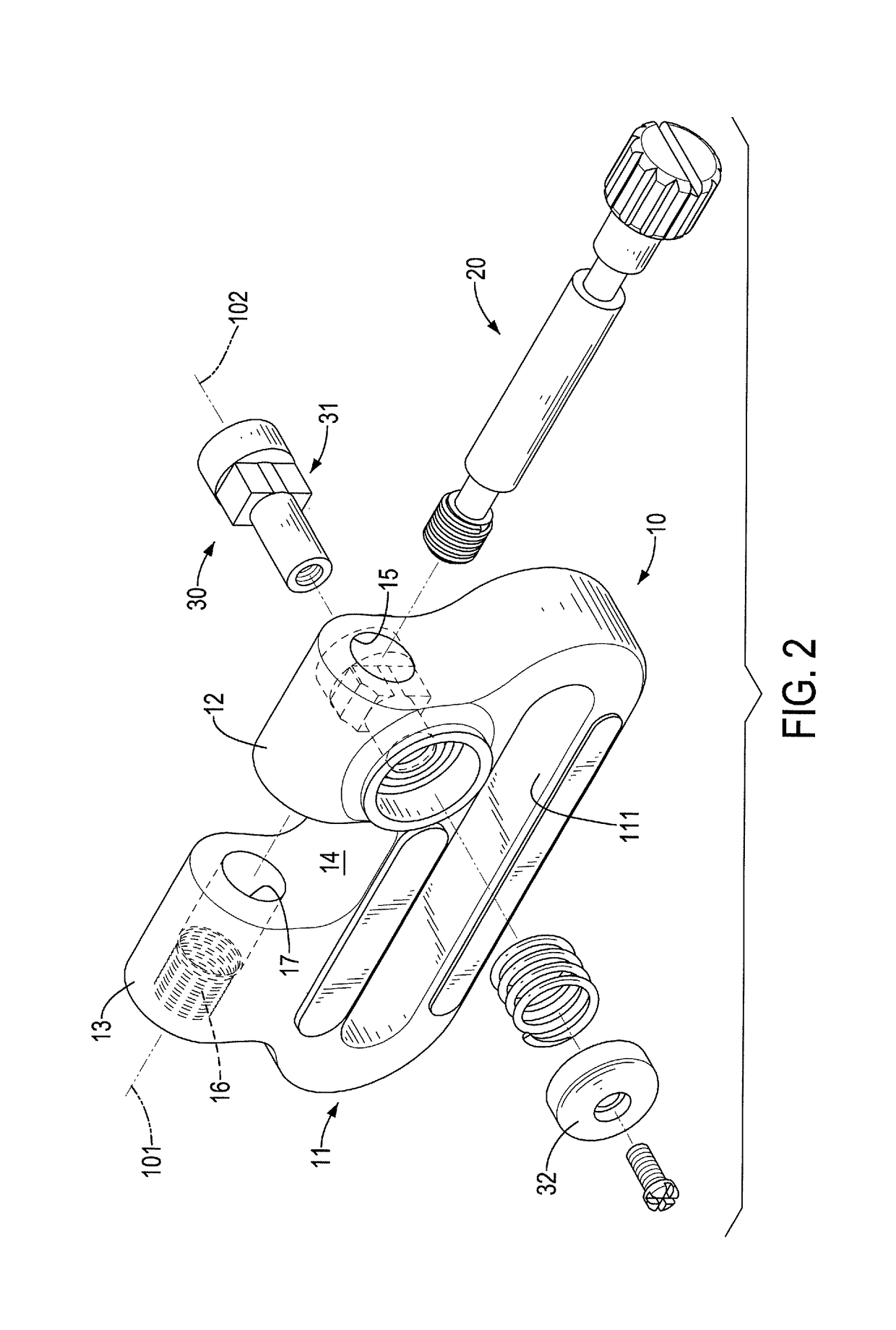
[0022]With reference to FIGS. 1 and 2, a swivel in accordance with the present invention has a main body 10, a longitudinal locking unit 20, and a lateral locking unit 30. The longitudinal locking unit 20 and the lateral locking unit 30 are mounted to the main body 10.

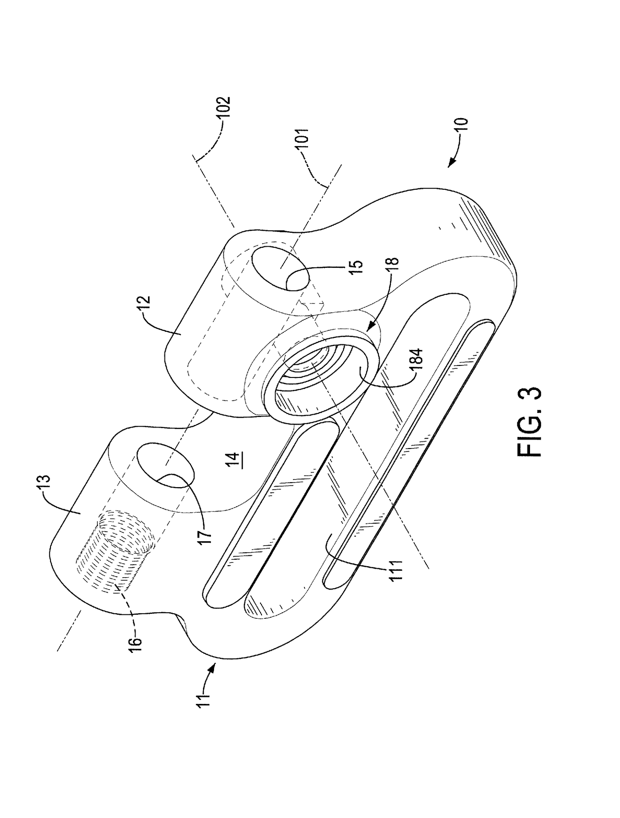
[0023]With reference to FIGS. 3, 6, and 7, the main body 10 has a longitudinal axis 101, a lateral axis 102, a ring portion 11, a mounting portion 12, a screwing portion 13, an accommodating gap 14, a through hole 15, a threaded hole 16, a connecting hole 17, and a receiving space 18. The longitudinal axis 101 and the lateral axis 102 of the main body 10 are perpendicular to each other. The ring portion 11 has a passing hole 111 formed through the ring portion 11 along a direction that is parallel to the lateral axis 101 of the main body 10. The passing hole 111 is an elongated hole extending along a direction that is parallel to the longitudinal axis 101 of the main body 10. The mounting portion 12 is connected to the...


PUM


Abstract

A swivel has a main body, a longitudinal locking unit, and a lateral locking unit. The main body has a longitudinal axis, a lateral axis being perpendicular to the longitudinal axis, an accommodating gap, a through hole, a threaded hole, and a receiving space. The accommodating gap is disposed between and communicates with the through hole and the threaded hole. The receiving space is disposed along the lateral axis and communicates with the through hole. The longitudinal locking unit has a shaft mounted through the through hole and screwed with the threaded hole. The lateral locking unit has a lateral locking component mounted in the receiving space and able to block the shaft to prevent the shaft from falling off from the accommodating gap. The swivel is capable of multiple locking manners to securely connect a belt and a heavy object.

Description

BACKGROUND OF THE INVENTION1. Field of the Invention[0001]The present invention relates to a swivel to connect two objects, and more particularly to a swivel with triple locking mechanisms for connecting heavy objects.2. Description of Related Art[0002]A swivel is a coupling device to connect two objects and to allow the two objects to pivot relative to each other.[0003]With reference to FIGS. 11 and 12, a conventional swivel 60 is connected to a first object 70 with an assembling mount 71 and a second object 80. For instance, the first object 70 may be a gunstock, and the second object 80 may be a gun sling. The swivel 60 has a first component 61, a second component 62, and a locking screw 63. The first component 61 has a connecting portion 611, a pivoting pin 612, and a ring portion 613. The connecting portion 611 has two opposite ends. The pivoting pin 612 has two opposite ends, and one of the two opposite ends of the pivoting pin 612 is fixed to one of the two opposite ends of t...

Claims


Application Information

Patent Timeline
IPC IPC(8): A44B13/00F41C33/00F16G15/08
CPCA44B13/0029F16G15/08F41C33/002F41C23/02F16G15/06
Inventor LIN, SHU-CHAN
Owner LIN SHU CHAN
Why Eureka
Try Eureka