Leak detection formula, analyzer and methods of use
What is Al technical title?
Al technical title is built by PatSnap Al team. It summarizes the technical point description of the patent document.
a leak detection and analyzer technology, applied in the field of leak detection, can solve the problems of color change inability to determine the exact location, and break the bubble(s) at the leak site, and achieve the effect of fast and accurate leak testing
Active Publication Date: 2019-03-05
AUTOMOTIVE TEST SOLUTIONS
View PDF36 Cites 3 Cited by
Summary
Abstract
Description
Claims
Application Information
AI Technical Summary
This helps you quickly interpret patents by identifying the three key elements:
Problems solved by technology
Method used
Benefits of technology
[0014]What is needed is a method and apparatus that can quickly and accurately find leaks within sealed systems and is not subject to the hole size limitation of smoke based leak detection systems. These leaks that must be located can be large (greater than 0.040″ in diameter), or small leaks (down to at least 0.001″ in diameter), or anywhere in between, and can be located along a seam or molding line, at connection points between components, or due to the porosity of the material, or be so small that the human eye cannot see them. What is also needed are systems that can test both low pressure and high pressure systems at their working pressure. What is further needed is an apparatus and method that does not require smoke generating machines or the chemicals used in generating the smoke, and can be used in varying lighting conditions (including poor lighting) and in the presence of moving ambient air. The present invention accomplishes these goals.SUMMARY OF THE INVENTION
[0015]The present invention allows fast, accurate leak testing to be done in the field, in varying lighting conditions (including poor lighting), where the ambient air is moving, and without the need for a smoke generating machine or the associated chemicals (including a fluorescent dye). Hole sizes as small as 0.001″ in diameter can be repeatedly detected. It accomplishes this by the use of a gas from a source external to the system being tested, the pressure of which can be set or adjusted depending upon the application, a gas sensor and a leak finding composition of matter which foams (or is in the form of a foam) on the surface(s) being tested for leaks.
Problems solved by technology
While the detector can quickly and easily locate the general area (base location) of the leak, it may not be able to determine the exact location.
However, it has been determined that a large leak size, or sufficiently high pressure, or both, will allow enough gas to be released that the foam cannot hold the pressure and the bubble(s) indicating the leak location will pop almost immediately.
However, even with greater surface tension, the combination of leak size and applied pressure can break the bubble(s) that indicate leakage.
Either of these would result in a color change at the leak site due to the leak finding solution.
Method used
Image
Click on the blue label to locate the original text in one second.
Reading with bidirectional positioning of images and text.
Examples
Embodiment Construction
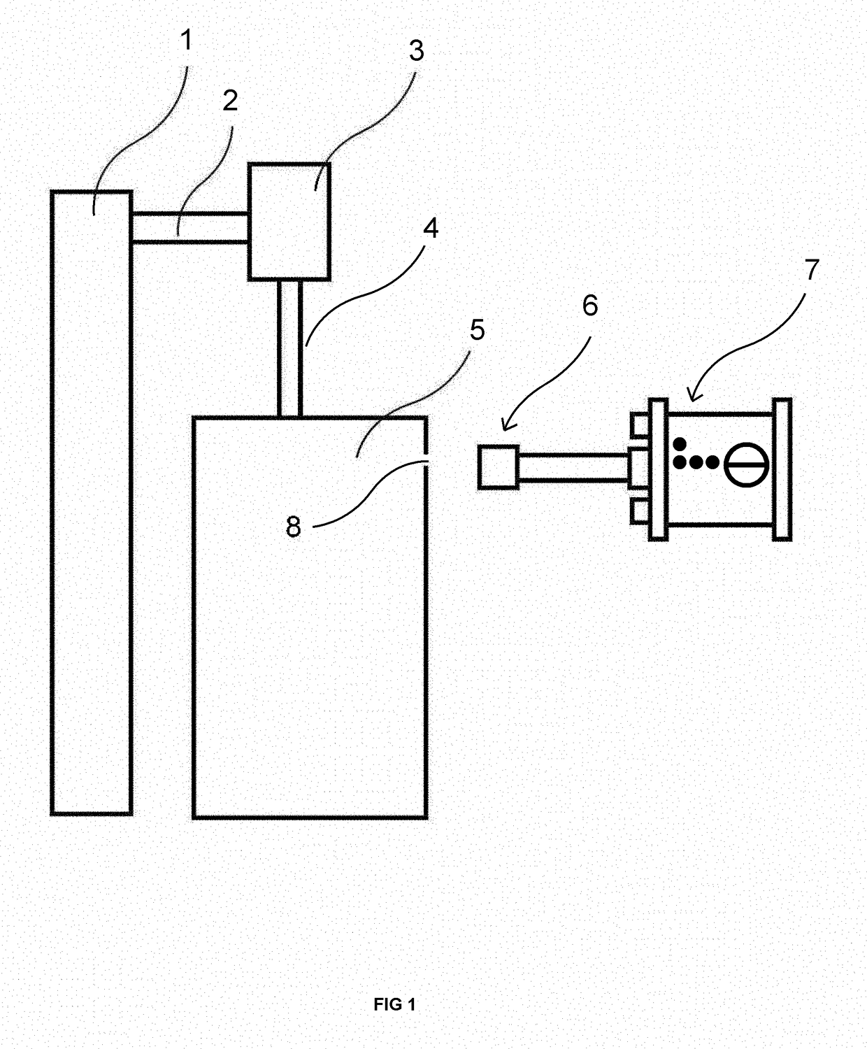
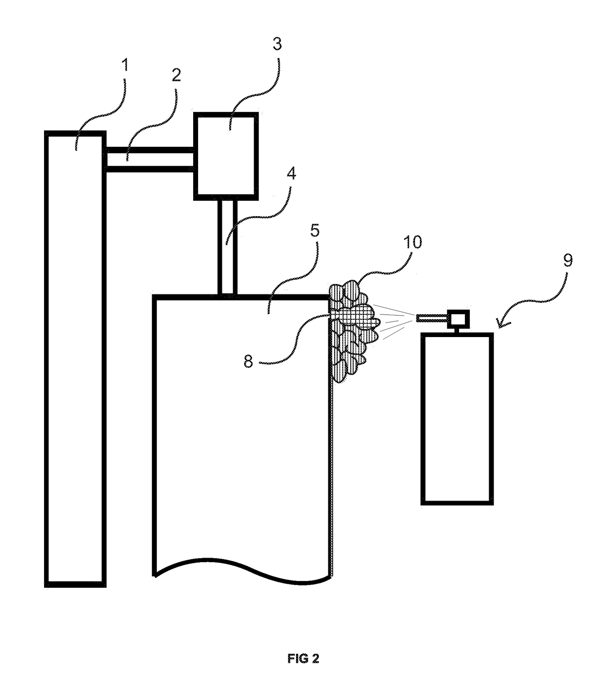
[0031]FIGS. 1-2 illustrate the leak detection system of the present invention, including the application of the foam. In FIG. 1 the CO2 pressurized bottle 1 is connected to a conventional pressure regulator 3 through hose 2. In operation, the service person will adjust pressure regulator 3 to the correct pressure for the system being tested. Hose 4 connects to sealed system 5. Thus, the pressure regulator 3 feeds CO2 from bottle 1 into sealed system 5 through hose 4. If one or more leaks are present in sealed system 5 then CO2 will escape out of the leak site(s) into the surrounding area. As illustrated, sealed system 5 has a leak at leak site 8 which leaks CO2 into the surrounding area.
[0032]After pressurizing system 5, a service person looking for leakage then moves CO2 detector 7 with sensor 6 round the sealed system 5. Where CO2 is leaking out of sealed system 5, sensor 6 detects the presence of this gas in the surrounding area. Detector 7 reads the sensor's voltage change that ...
PUM
Abstract
Detecting a leak from a site in a sealed system with a source of pressurized gas which is capable of passing through the site, a composition of matter which adheres to the surfaces of the system and which is capable of showing the presence of the gas escaping from the site. The method includes: injecting gas into the system to a pressure in excess of the surrounding pressure, and covering the external surface with the composition to identify the location of the site by the interaction of the escaping gas with the composition. The composition is foam that includes a surfactant which forms a least one bubble in the presence of escaping gas and an indicator which changes color in the presence of the escaping gas. The leak is an opening down to at least the size of a hole 0.001'' in diameter. A gas detector may also be used.
Description
CROSS-REFERENCE TO RELATED APPLICATIONS[0001]This application is a continuation of provisional application Ser. No. 61 / 759,782, entitled “Leak Detection Analyzer,” filed Feb. 1, 2013. This application is also a continuation-in-part of application Ser. No. 13 / 789,179, now U.S. Pat. No. 9,390,565, entitled “Leak Verification and Detection for Vehicle Fuel Containment Systems”, filed Mar. 7, 2013, which is a continuation-in-part of application Ser. No. 13 / 115,516, entitled “Leak Verification and Detection for Vehicle Fuel Containment Systems”, filed Mary 25, 2011 which, in turn, is a continuation of provisional application Ser. No. 61 / 348,078, entitled “Leak Verification and Detection for Vehicle Fuel Containment Systems”, filed May 25, 2010. This application claims the priority to and the benefit of all four applications.FIELD OF INVENTION[0002]This invention relates to the field of leak detection, more particularly to finding small size leaks in sealed systems, quickly and accurately...
Claims
Application Information
Patent Timeline
Application Date:The date an application was filed.
Publication Date:The date a patent or application was officially published.
First Publication Date:The earliest publication date of a patent with the same application number.
Issue Date:Publication date of the patent grant document.
PCT Entry Date:The Entry date of PCT National Phase.
Estimated Expiry Date:The statutory expiry date of a patent right according to the Patent Law, and it is the longest term of protection that the patent right can achieve without the termination of the patent right due to other reasons(Term extension factor has been taken into account ).
Invalid Date:Actual expiry date is based on effective date or publication date of legal transaction data of invalid patent.
Patent Type & Authority Patents(United States)
IPC IPC(8): G01M3/22G01M3/04
CPCG01M3/042G01M3/226
Inventor THOMPSON, BERNIE C.PEDERSON, NEAL R.LEY, KENNETH D.THOMA, STEVEN G.