Curved display panel and display device containing the same

a display panel and display device technology, applied in non-linear optics, instruments, optics, etc., can solve problems such as display problems of curved display panels

Active Publication Date: 2019-03-05
BOE TECH GRP CO LTD
View PDF17 Cites 2 Cited by
  • Summary
  • Abstract
  • Description
  • Claims
  • Application Information

AI Technical Summary

Benefits of technology

[0005]The present disclosure provides a curved display panel. By using the disclosed curved display panel, display difference between the subpixels, located at the bending or curving locations and disposed with spacers, and other subpixels may be reduced.

Problems solved by technology

However, conventional curved display panel is susceptible to issues including yellowing and appearing dark at bending locations, which can cause impaired display of the curved display panel.

Method used


Image

  • Curved display panel and display device containing the same
  • Curved display panel and display device containing the same
  • Curved display panel and display device containing the same

Examples


embodiment

[0055 One

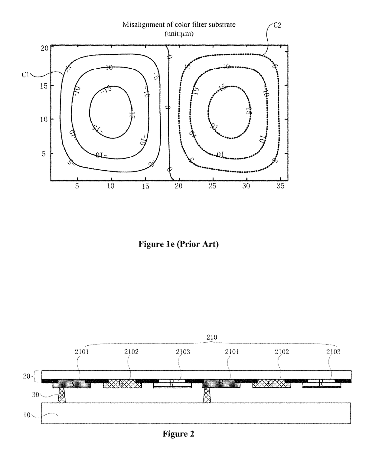
[0056]Exemplary light-transmitting holes may be formed to reduce the effective light-filtering areas of the second light-filtering unit 2102 and the third light-filtering unit 2103. Monochromatic green (G) light, formed by the white light emitted by the backlight source passing through a second light-filtering unit 2102, may have a reduced intensity. Monochromatic red (R) light, formed by the white light emitted by the backlight source passing through a third light-filtering unit 2103, may have a reduced intensity. Thus, human eyes may recognize the intensities of the green (G) light and the red (R) light to be comparable with the blue (B) light, which is formed by the white light passing through a first light-filtering unit 2102 with a reduced effective display area. The intensities of the blue (B) light, green (G) light, and red (R) light may reach a balanced state. The reduced effective display area may be caused by the spacer disposed at the location of the first light-...

embodiment two

[0064

[0065]White light-filtering subunits may be formed to reduce the effective light-filtering area of the second light-filtering unit 2102 and / or the effective light-filtering area of the third light-filtering unit 2103. A white light-filtering subunit may convert light, e.g., green light and red light, passing through the white light-filtering subunit to white light. The chromatic green (G) light, formed by the white light emitted by the backlight source and passing through a second light-filtering unit 2102, may have a decreased intensity. The chromatic red (R) light, formed by the white light emitted by the backlight source and passing through a third light-filtering unit 2103, may have a decreased intensity. Thus, human eyes are not able to distinguish the intensity differences of different monochromatic light. The intensities of the blue (B) light, green (G) light, and red (R) light may reach a balanced state. Specifically, human eyes may recognize the blue (B) light, formed ...

embodiment three

[0076

[0077]The light transmission rate of a first light-filtering unit 2101 may be increased by reducing the thickness of the first light-filtering unit 2101 and / or increasing the thickness of a second light-filtering unit 2102. In some embodiments, the light transmission rate of a first light-filtering unit 2101 may be increased by reducing the thickness of the first light-filtering unit 2101 or increasing the thickness of a third light-filtering unit 2103. Thus, the green (G) light, formed by the white light emitted by the backlight source and passing through the second light-filtering unit 2102, and the red (R) light, formed by the white light emitted by the backlight source and passing through the third light-filtering unit 2103, may have same or comparable brightness level as the blue (B) light. The blue (B) light is formed by the white light emitted by the backlight source passing through the first light-filtering unit 2101, which has a decreased effective display area caused ...


PUM

PropertyMeasurementUnit
diameteraaaaaaaaaa
areaaaaaaaaaaa
diameteraaaaaaaaaa

Abstract

The present disclosure provides a curved display panel, including a first substrate and an opposing second substrate, the first substrate including a light-filtering layer. The light-filtering layer includes a first light-filtering unit, a second light-filtering unit, and a third light-filtering unit in a pixel unit; and at least one of an effective light-filtering area of the second light-filtering unit and an effective light-filtering area of the third light-filtering unit is larger than or smaller than an effective light-filtering area of the first light-filtering unit. A ratio of the effective light-filtering area of the second light-filtering unit to the effective light-filtering area of the first light-filtering unit is greater than or equal to about 0.9 and less than about 1, or is greater than about 1 and less than or equal to about 1.1.

Description

CROSS-REFERENCES TO RELATED APPLICATIONS[0001]This PCT patent application is a national phase entry under 35 U.S.C. § 371 of International Application No. PCT / CN2016 / 094870, filed on Aug. 12, 2016, which claims priority of Chinese Patent Application No. 201610006704.9, filed on Jan. 5, 2016. The above enumerated patent applications are incorporated by reference herein their entirety.TECHNICAL FIELD[0002]The present invention generally relates to the display technologies and, more particularly, relates to a curved display panel and a display device containing the display panel.BACKGROUND[0003]As the display technology advances, curved display panels have been used in various applications. The curvature of a curved display panel is often comparable to the curvature of viewer's retina, so that curved display panels can provide better display effect. Curved display panels have drawn widespread attention in the market and industry.[0004]However, conventional curved display panel is susce...

Claims


Application Information

Patent Timeline
Patent Type & Authority Patents(United States)
IPC IPC(8): G02F1/1335G02F1/1333G02F1/1339
CPCG02F1/133305G02F1/133514G02F1/133512G02F1/1339
Inventor ZHAO, WEILI
Owner BOE TECH GRP CO LTD
Why Eureka
Try Eureka