Detecting a fault, in particular a transient fault, in an electrical network

a technology of transient faults and fault detection, applied in emergency protective circuit arrangements, frequency measurement arrangements, instruments, etc., to achieve the effect of optimizing fault detection and mitigating the drawbacks of existing fault detection devices

Active Publication Date: 2019-03-12
SCHNEIDER ELECTRIC IND SAS
View PDF12 Cites 1 Cited by
  • Summary
  • Abstract
  • Description
  • Claims
  • Application Information

AI Technical Summary

Problems solved by technology

Furthermore, some techniques require a significant sampling or a computation period that allows for the detection of the fault only over the next period of the current, or even not at all for transient events.

Method used


Image

  • Detecting a fault, in particular a transient fault, in an electrical network
  • Detecting a fault, in particular a transient fault, in an electrical network
  • Detecting a fault, in particular a transient fault, in an electrical network

Examples


Embodiment Construction

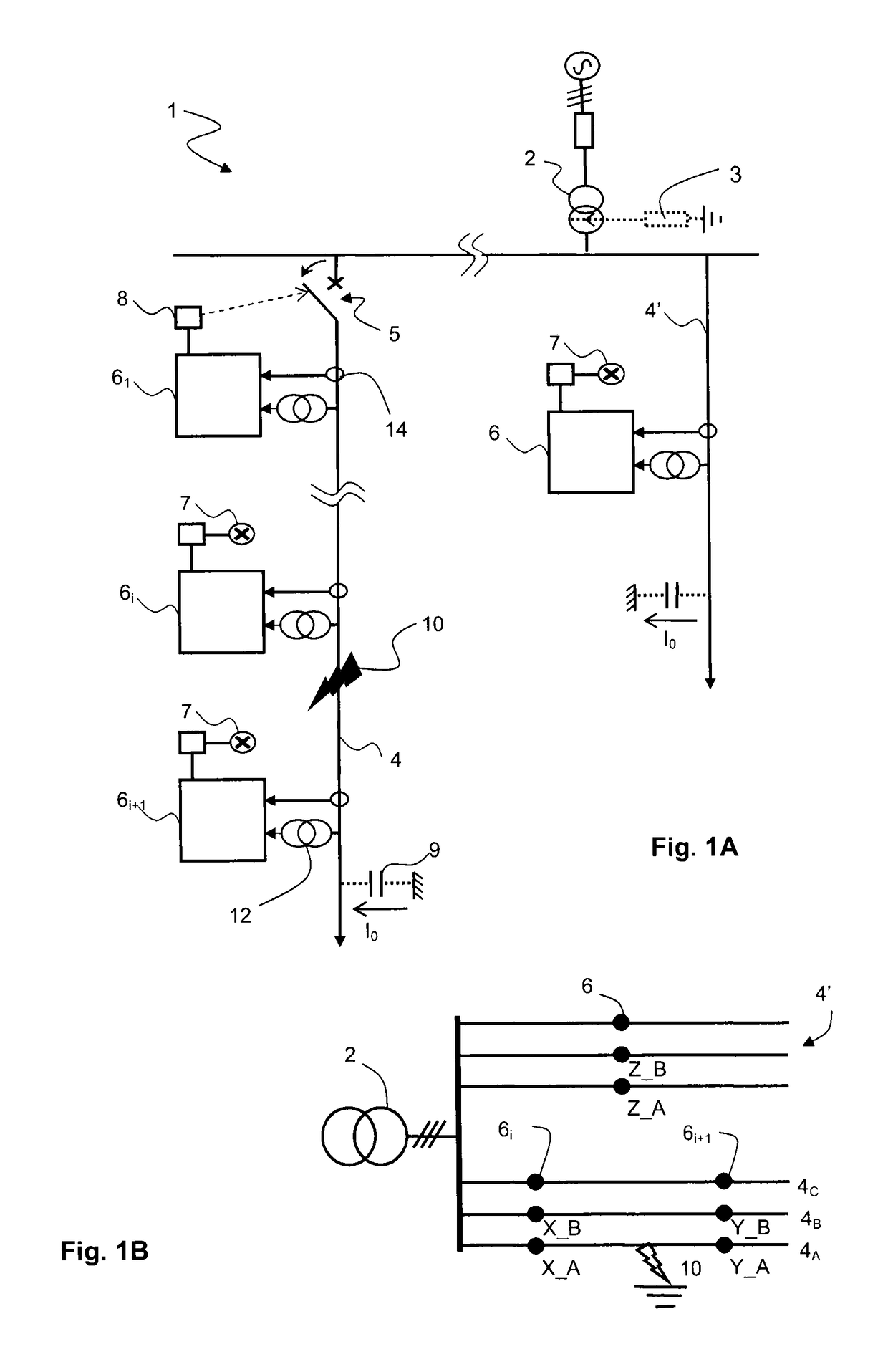
[0024]The invention will be described for a balanced three-phase network 1 with compensated or insulated neutral, in which each line 4, 4′ comprises three overhead phase conductor 4A, 4B, 4C, the secondary of the transformer 2 being linked to the earth via a Petersen coil 3 (FIG. 1A), or not being linked thereto (FIG. 1B), and the zero sequence current I0 is zero in the absence of any fault. Zero sequence current I0 should be understood to mean, to within a possible factor of three, the vector sum of the different phase currents, or even the current corresponding to the instantaneous resultant of the phase currents, sometimes called residual current, which, if appropriate, corresponds to the ground fault current or to the leakage current. It should be noted that it is possible to get away from this situation, notably with a non-zero sequence current / voltage, and the network can comprise another number of phases; moreover, the neutral regime need not be compensated.

[0025]As is known,...


PUM


Abstract

In order to determine the occurrence of a fault, notably transient, in an electrical distribution network, a method and a device are developed based on the determination of the frequency (f) of the current signal circulating in a phase of the network. Notably, the difference between the determined frequency (f) and the natural frequency (f0) of the network is compared to a threshold.

Description

TECHNICAL FIELD[0001]The invention relates to the detection of a fault, for example to earth, notably in an overhead network; the method according to the invention relies on the analysis of the frequency of the current signal.[0002]According to another aspect, the invention relates to a detection device suitable for implementing the above method. In particular, the fault detection device comprises means that make it possible to determine the frequency of the current signal from a minimum number of values, notably three.STATE OF THE ART[0003]The fault detection devices in three-phase networks make it possible to trigger the protection of the loads and / or assist in the locating of said faults. For example, FIG. 1A represents a diagram of a medium voltage electrical distribution network 1 which comprises a three-phase transformer 2, the secondary of which can comprise a common neutral conductor generally connected to the earth through an impedance 3 (in the case of a network with insul...

Claims


Application Information

Patent Timeline
Patent Type & Authority Patents(United States)
IPC IPC(8): G01R31/02G01R23/15H02H3/46H02H7/26G01R23/02G01R31/50
CPCG01R31/024G01R23/15H02H3/46H02H7/263G01R31/02G01R23/02G01R31/50H02H3/16H02H7/26
Inventor VERNEAU, GUILLAUMEBAUMES, NATHALIE
Owner SCHNEIDER ELECTRIC IND SAS
Why Eureka
Try Eureka