[0035] The overall structure of a high performance
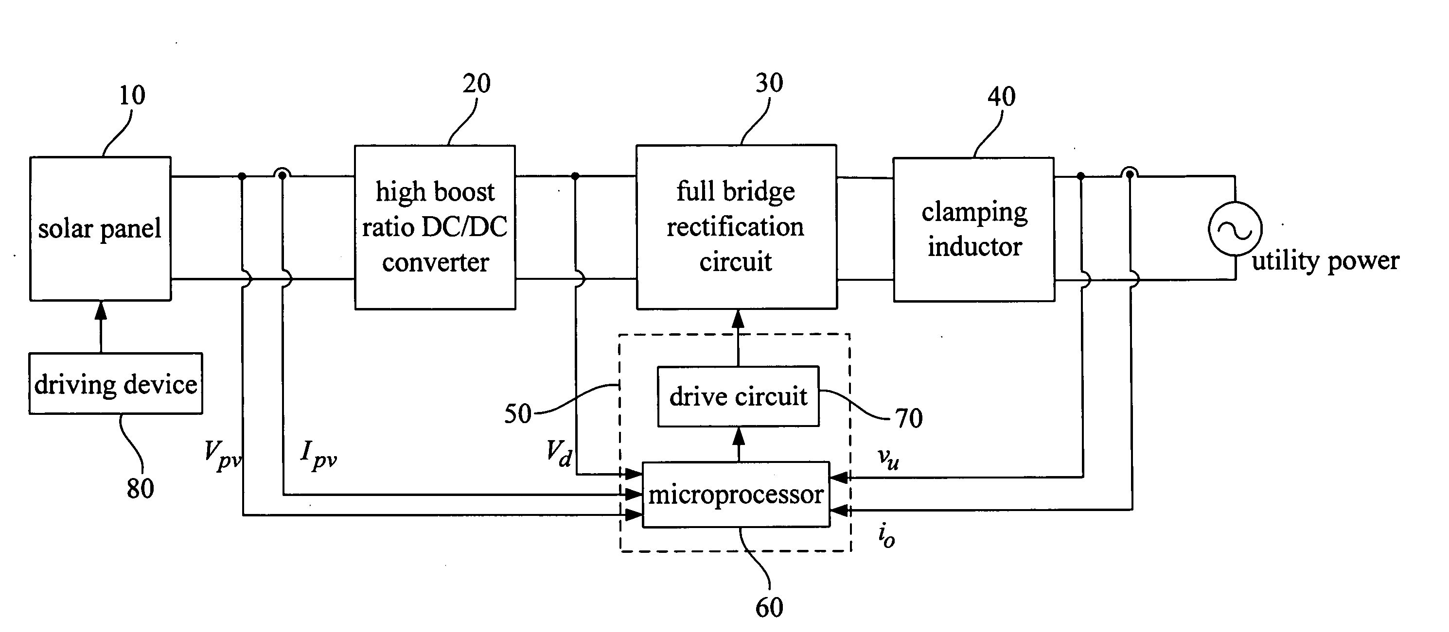
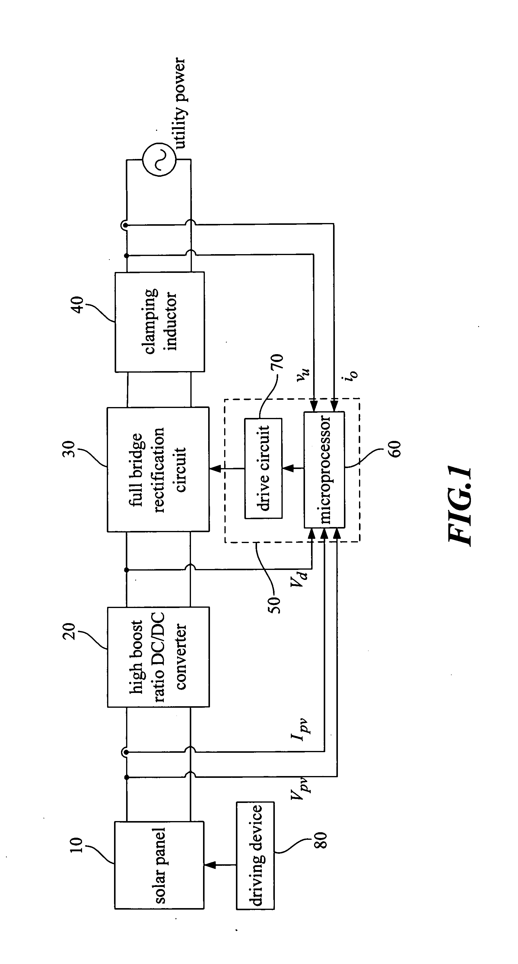
solar energy conversion system proposed by the present invention is shown in FIG. 1. The solar panel 10 absorbs solar energy, and after the photovoltaic conversion output
DC voltage Vpv is fed into the high boost ratio DC /
DC converter 20; the structure of the high boost ratio DC /
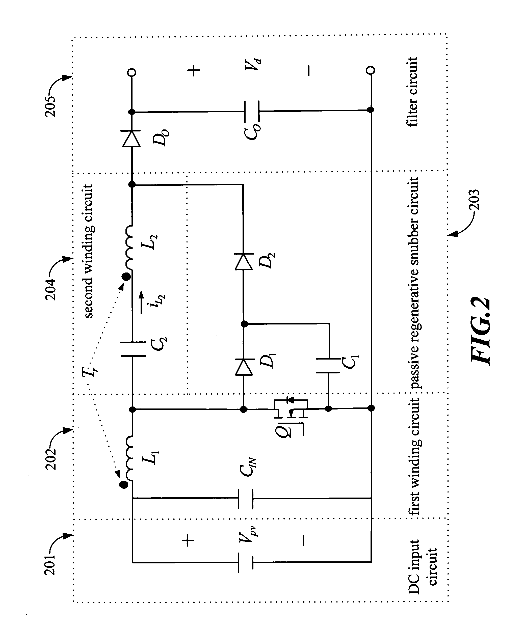
DC converter 20 is shown in FIG. 2. When the power
semiconductor switch Q of the first winding circuit 202 is turned on, the
DC voltage Vpv of the input circuit 201 will store energy in the first winding L1 of the
coupling inductor Tr; at the same time, because the bi-directional current passage of the second winding L2 of the
coupling inductor Tr of the second winding circuit 204, it's coupled the voltage VL<sub2>2 < / sub2>(is positive at the moment), plus the voltage of clamping
capacitor C1 of the passive regenerative
snubber circuit 203, through the power
semiconductor switch Q and the discharging
diode D2, the charge
high voltage capacitor C2 (charging current is −iL<sub2>2< / sub2>). The moment the power semiconductor switch Q is turned off, the current of the first winding circuit 202 leaves the power semiconductor switch Q and flow through the clamping
diode D1 of the passive regenerative
snubber circuit 203 into the clamping
capacitor C1 of the circuit. The current iL<sub2>2 < / sub2>of the second winding circuit 204 has to flow through the clamping diode D1 and the discharging diode D2, to release energy stored by leakage induction of the second winding L2 of the
coupling inductor Tr; and the
high voltage capacitor C2 absorbs the energy; after releasing induction energy of the second winding L2, according to the theorem that the
magnetic flux does not extinguish, the first winding excited current will reverse the second winding current iL<sub2>2< / sub2>, the rectifying diode DO of the filter circuit 205 is turned on and the current iL<sub2>2 < / sub2>flows into the
filter capacitor CO of the circuit 205, such that a stable
DC voltage Vd is obtained. This overcomes the drawback of the single-stage type
solar energy conversion system in which the voltage on the
DC bus bar is affected by the change of load; The circuit connects with the
full bridge rectification circuit 30 and the DC voltage Vd can be regarded as a fixed value, decoupling from the subsequent inverter, which simplifies design of the inverter
control system.
[0057] Although
Sun tracking can maximize
radiation on a solar penal and improve the system efficiency but difficult to implement, such as, the sensing technique, the
elimination of external interferences, the reliability and the cost. Commonly used Sun tracking method mounts the photo sensor on both sides of the solar panel and by adjusting the angle of the panel until signals by a driving device 80 from both sides are equal, the panel is directly facing the Sun. However, adjustment of photo sensing device is not easy and sensor's character changes through aging. The present invention proposes a Sun
tracking system, which utilizes the fact that
open circuit voltage of a solar panel is proportional to radiation strength of the Sun, and by adjusting angle of the panel and measuring the
open circuit voltage, the
microprocessor can determine if the panel is facing the Sun and send corresponding
control signal. The method only use
open circuit voltage of a solar panel to track
position of the Sun, and since the Sun moves slowly, ascending angle is unchanged in a month and total change is less than ±10° in a year, the
tracking system does not need to change tilting angle, and a
single axis position control can accomplish the purpose of collecting maximum radiation. The control process is shown in FIG. 7, where Voc[n] and Voc[n−1] are current and previous open circuit voltage; ΔVoc is the changing size of the open circuit voltage; during a day the Sun only moves from East to West, the process starts with
clock wise and one degree per tr the second speed rotation to vary the open circuit voltage and to determine if continue to rotate in order to maximize the radiation reception; if over rotation or outside environment change(tree shadow) cause the open circuit voltage decrease, the system will rotated back to the previous position and wait tw second before resume tracking.
[0058] For the conventional maximum power tracking method, the
Perturbation and Observation Method is widely used due to its simplicity and no need for using
system parameters; however, the perturbation quantity is not easy to chose, and a larger perturbation quantity can improve the response speed but the perturbation will not stop even when the solar panel reaches a maximum
power output; the perturbation around the maximum power point will causes an energy loss; a smaller step can be used to improve the perturbation, but when the temperature or the radiation drastically changes, the characteristic curve changes, and the maximum power point shifts, all cause a
slow response in tracking the new maximum power point; it will cause energy loss too; therefore, it is a balancing act on the
response time and the energy loss when choosing perturbation quantity. The present invention proposes an Adaptive Step-
Perturbation Method, through the feedback of the output voltage and the current of the solar panel, the
microprocessor can calculate varying quantities of the output voltage and power of the solar panel and adjust the perturbation steps based on their relationship according to the system condition; this will effective improves the conventional
Perturbation and Observation Method, and speed up the
maximum power point tracking and reduce the energy loss.


