Energy-efficient solar-powered outdoor lighting

a solar energy and outdoor lighting technology, applied in the direction of dc source parallel operation, lighting support devices, built-in power, etc., can solve the problems of load “turning itself off and battery damage, and achieve the effect of effective operation and service for users

Inactive Publication Date: 2015-01-22
INOVUS SOLAR
View PDF3 Cites 297 Cited by
  • Summary
  • Abstract
  • Description
  • Claims
  • Application Information

AI Technical Summary

Benefits of technology

[0003]The invention is an energy-efficient system comprising at least one outdoor light, powered by solar panels and / or batteries, and may include other electrically-powered devices. The invented energy management system actively manages the available energy and controls the power or energy delivered to the load, in ways that allow said light and / or other devices to effectively operate and serve the users even through low-sun-shine days, weeks, or months. The preferred adaptations actively control battery charging, and actively control power delivered to the load, in contrast to conventional control methods wherein the system is passively controlled by the load. Thus, the preferred embodiments protect the batteries of the system from draining below their low-end threshold, even when operating over extended periods of low-sunshine days, whereas the conventional control methods allow the load to draw more energy than is available in the storage system / battery and frequently result in the load “turning itself off” and in battery damage.

Problems solved by technology

Thus, the preferred embodiments protect the batteries of the system from draining below their low-end threshold, even when operating over extended periods of low-sunshine days, whereas the conventional control methods allow the load to draw more energy than is available in the storage system / battery and frequently result in the load “turning itself off” and in battery damage.

Method used


Image

  • Energy-efficient solar-powered outdoor lighting
  • Energy-efficient solar-powered outdoor lighting
  • Energy-efficient solar-powered outdoor lighting

Examples


example

Apparatus and Methods of Active Control for Energy-Efficient Lighting

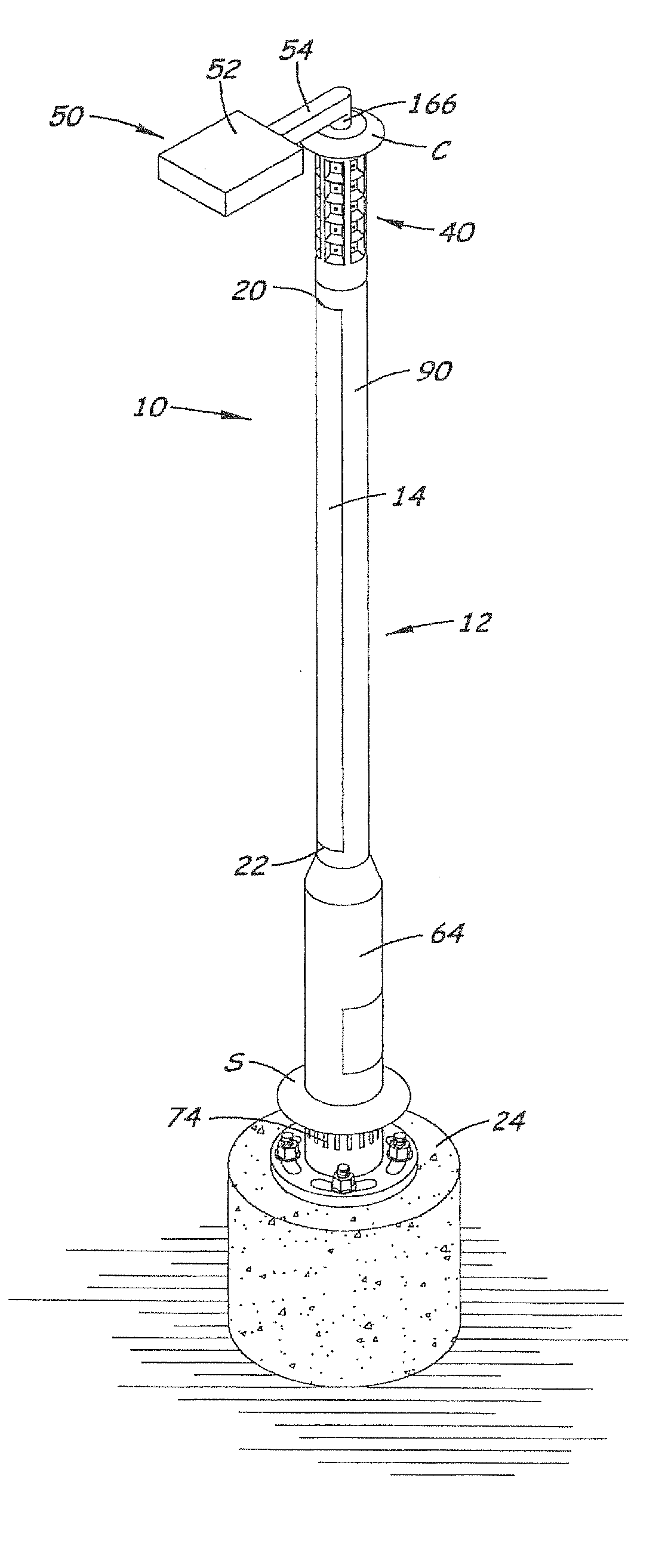
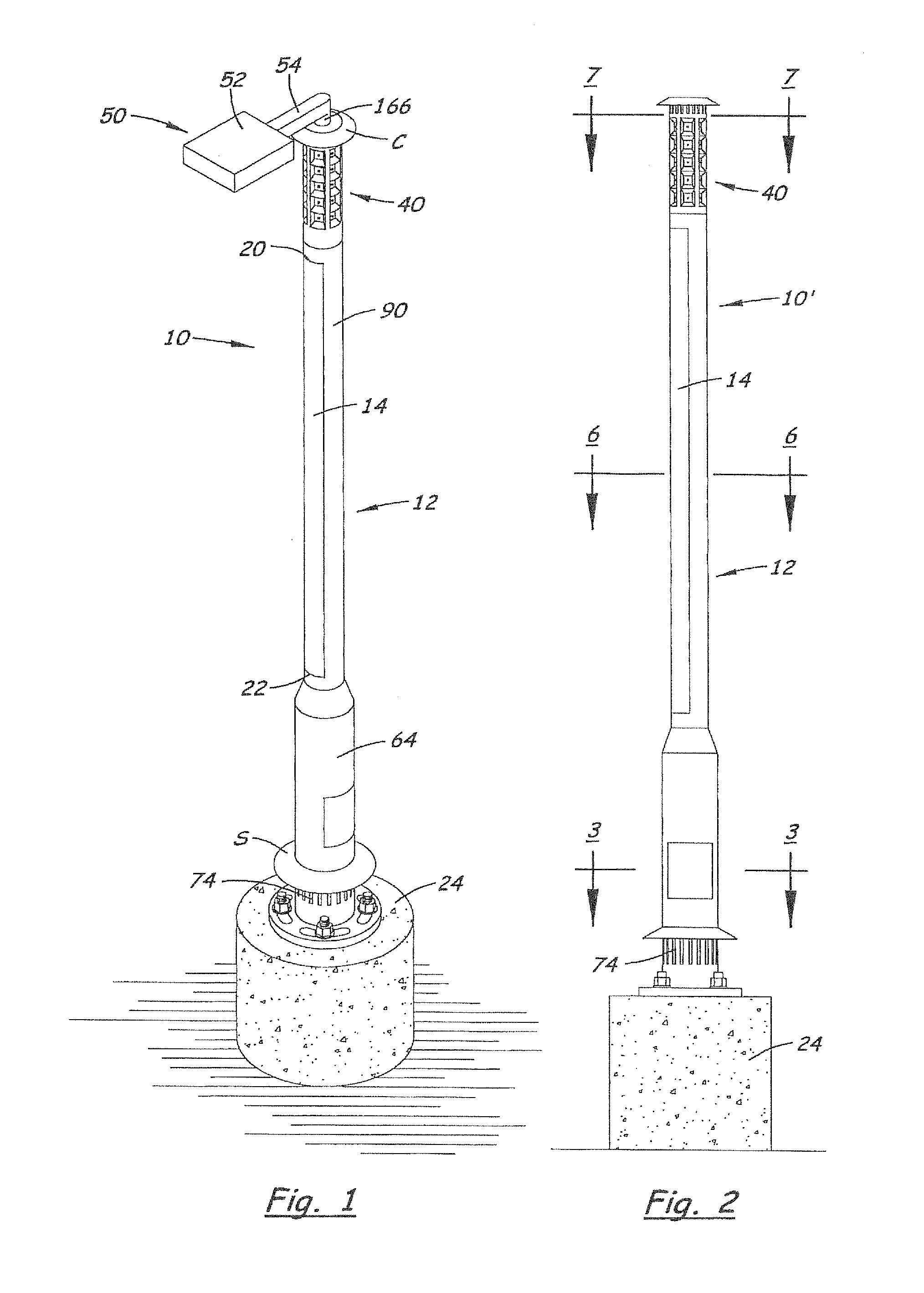
[0388]The preferred apparatus comprises an LED-based luminaire, a photocell, a control board, a charge controller, a solar collector (or solar collector panel) a battery subsystem (composed of 6-8 batteries, a battery enclosure and wiring harnesses), three motion sensors, and the pole assembly. See FIG. 37.

[0389]The solar collector captures light during daytime hours and passes it onto the charge controller. The charge controller manages the power provided from the solar collector to optimize the power to be stored in the batteries. The batteries hold stored electrical energy and release it to power the LED luminaire and other system electronics. Various modes of energy release are determined and managed by the control board. The control board uses input from the photocell to determine when to turn the luminaire on (and off at dawn), and uses energy-saving algorithms to manage energy to the luminaire. These algorit...

example normal

Mode Operation:

[0418]As portrayed in FIG. 46, toward the end of the day, as it starts to get dark, the photocell turns on the light at 100% (factory preset) normal power. It stays at 100% for two hours (factory preset) then dims down to 25% brightness (factory preset) for the balance of the night w / motion sensor over-ride. If motion is detected it immediately brightens up to 100% for 10 minutes after the last-detected motion. It then dims back down to the lower setting over one minute. Towards dawn, the light will brighten back up to full brightness approximately 30 minutes (factory preset) prior to dawn. When the photocell threshold for dawn is crossed, the light will turn off.

Example Energy-Savings Mode Operation:

[0419]FIG. 47 portrays examples of how system conditions can be utilized to determine the appropriate energy modes based on current states to modify power delivered, to the light or other loads, beyond or instead of the “normal” changes over time shown in FIG. 46. For ex...

example 1

, Under Version C Programming:

[0463]Starting battery voltage (morning of November 1); Vsb=12.2V; Ending battery voltage (evening of November 1); Veb=13.1V; Factory pre-sets for Tk=120 & Tn=30 (dusk 2 hrs & pre-dawn 0.5 hr.); Dp=0.25; Mode=N1; and Light is turned on & off by the photocell.

[0464]Photocell turns the light on at 100% at dusk & remains on for 2 hours, at which time the light dims down to 25% power over the next minute. The light remains at the dimmed down light level state until the motion sensor is activated, at which time the light is brought back up to 100% for 10 minutes. The light then dims back down to 25% power over the next minute. The light dims back up to 100% 30 minutes pre-dawn and remains on until the photocell shuts the light off.


PUM

PropertyMeasurementUnit
diameteraaaaaaaaaa
voltagesaaaaaaaaaa
voltagesaaaaaaaaaa

Abstract

One or more outdoor lights may operate independently with sensing and control processes mainly on-pole, or may communicate as a networked array of poles, wherein a master / coordinating pole / node transmits signals from the networked array to a control station, and receive signals from the control station for the networked array, via call phone and / or satellite. Independent poles and / or the networked array of poles may be adapted for energy-saving processes; cooperation with the grid; renewable power production and storage by means of solar panels and associated batteries; and / or to provide Wi-Fi hot-spots, public safety alarms, information or data-analysis to the public or customers. An energy-saving active control system controls charging of the batteries and distribution of energy from the solar panel and / or the batteries, so that the batteries remain undamaged, and the light(s) remain operation even during the winter or other long periods of clouds and diffuse light. The active control of energy distribution by a load controller function may include dimming during the night, except when sensors detect motion, and, in extreme cloudy or diffuse-light periods, increasing increments of dimming and / or load shedding, to preserve the batteries and operability.

Description

[0001]This application is a continuation of U.S. Ser. No. 13 / 128,395, filed Oct. 6, 2011, which is a 371 National Phase Entry of PCT / US2009 / 64659 filed Nov. 16, 2009 and entitled “Energy-Efficient Solar-Powered Outdoor Lighting”, claiming priority benefit of U.S. Provisional Patent Application Ser. No. 61 / 114,993, filed Nov. 14, 2008 and entitled “Energy Efficient Lighting Control,” and claiming priority benefit of U.S. Non-Provisional patent application Ser. No. 12 / 533,701, filed Jul. 31, 2009, entitled “Wireless Autonomous Solar-Powered Outdoor Lighting and Energy and Information Management Network”, and issued as U.S. Pat. No. 8,588,830 on Nov. 19, 2013, the entire disclosures of said provisional application and said non-provisional application being incorporated herein by this reference. Above-listed application Ser. No. 12 / 533,701 claims priority benefit of Provisional Ser. No. 61 / 137,437, filed Jul. 31, 2008; Ser. No. 61 / 137,434, filed Jul. 31, 2008; Ser. No. 61 / 137,433, filed...

Claims


Application Information

Patent Timeline
Patent Type & Authority Applications(United States)
IPC IPC(8): F21S9/03H02J7/35F21S8/08H05B37/02H02J1/00
CPCF21S9/035F21S8/088F21W2131/103H02J1/00H02J7/355H05B37/0272H04W84/18F21V29/71H05B33/0809F21S9/043F21V23/04F21V21/03Y02B20/40F21S2/00Y10T307/25F21V14/02F21V29/763F21V29/83Y02B20/72Y02E10/50F21Y2101/02H01L31/052H05B37/034Y02B20/383H02S40/38H01L31/0203F21S8/085F21V29/004Y10T307/344F21S8/083H01L31/0521F21Y2115/10Y10T29/49002H05B47/22H05B47/19Y02D30/70Y02E10/76Y02E70/30H02J7/35Y02B20/30
Inventor MYER, SETH JAMISONCOOPERRIDER, PAUL H.GONZALEZ, DAVID
Owner INOVUS SOLAR
Why Eureka
Try Eureka