Wearable supporting structure for supporting ballistic protections and/or military equipment

a technology for supporting structures and ballistic protections, applied in protective equipment, clothing making applications, travelling articles, etc., can solve the problems of high liquid consumption, physical problems in short and long term, abrasions and localized traumas, etc., and achieve the effect of simple and inexpensiv

Inactive Publication Date: 2019-03-19
MECH LAB
View PDF12 Cites 2 Cited by
  • Summary
  • Abstract
  • Description
  • Claims
  • Application Information

AI Technical Summary

Benefits of technology

[0013]An object of the present invention is to provide a wearable supporting structure for supporting ballistic protections and / or military equipment, which allows the above needs to be met in a simple and inexpensive way.
[0018]Conveniently, the motorised adjustment means also comprise a worm screw-worm wheel transmission interposed between the motor and said rope transmission. The worm screw and worm wheel combination ensures a high reduction ratio and allows for the use of a motor with reduced power and size and rotating at high rotational speeds, so as to always obtain a sufficient output torque for a continuous and precise adjustment and distribution of the load.

Problems solved by technology

In known arrangements, under certain conditions, the entire war load weighs almost entirely on the shoulders of the user, causing, in use, abrasions and localized traumas due to unavoidable pressure and rubbing.
In other solutions, the load acts for the most part on the spine causing physical problems in the short and in the long term.
The ballistic protections, wrapping by nature and made of non-breathable materials, were experimentally shown to inhibit the natural thermoregulation; this entails high consumption of liquids, a risk of dehydration in demanding situations and, in any case, a proven decrease in the efficiency of the user.

Method used


Image

  • Wearable supporting structure for supporting ballistic protections and/or military equipment
  • Wearable supporting structure for supporting ballistic protections and/or military equipment
  • Wearable supporting structure for supporting ballistic protections and/or military equipment

Examples


Embodiment Construction

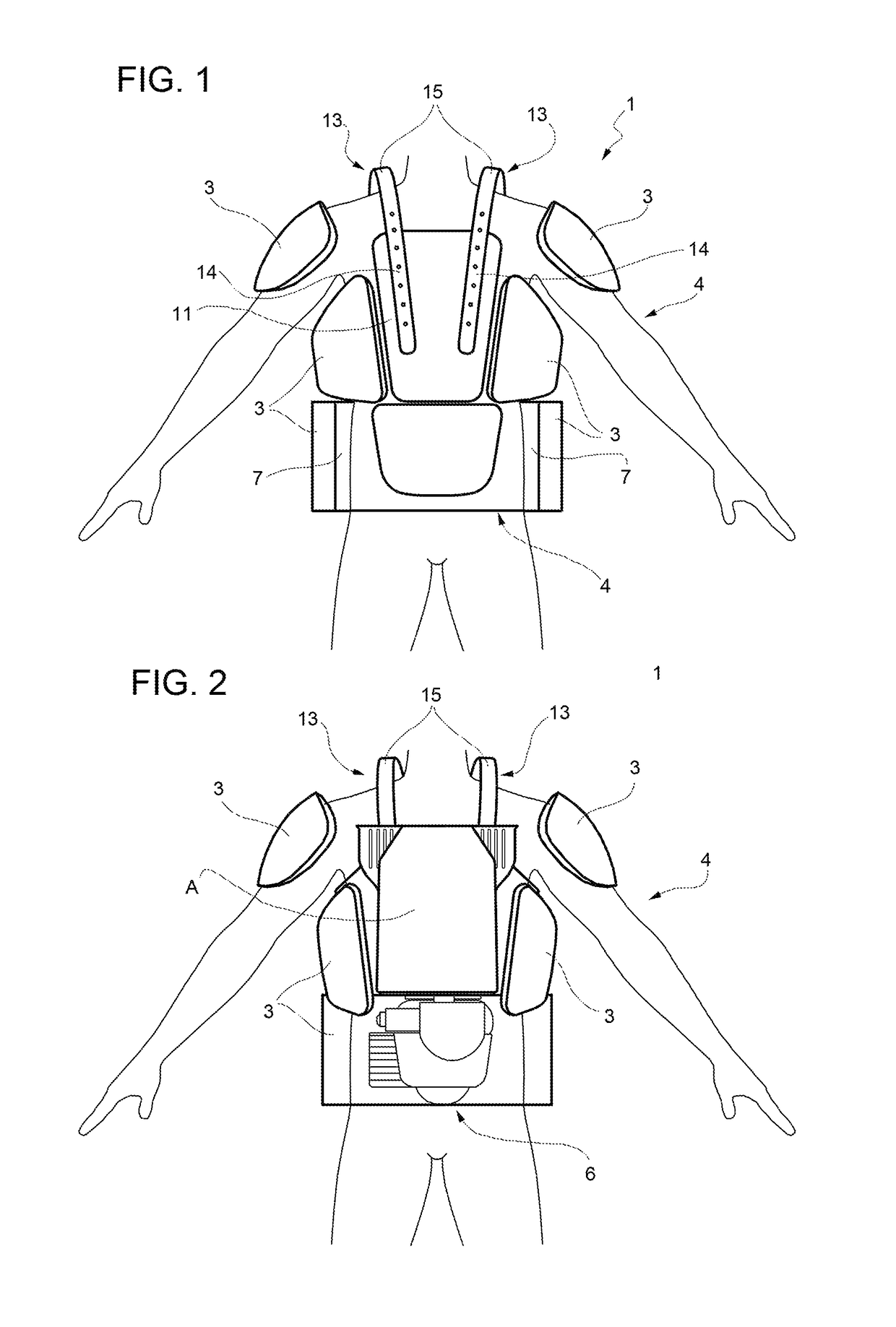
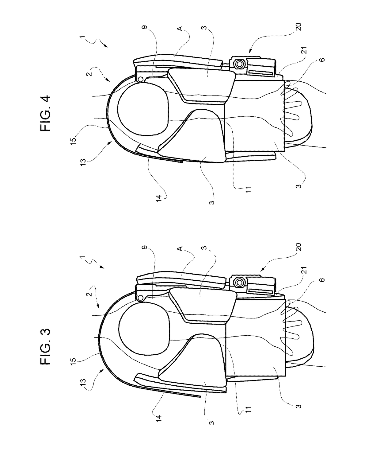
[0023]In FIGS. 1 to 4, 1 denotes, as a whole, a supporting structure for supporting ballistic protections 3 and / or military equipment, such as, for example, weapons, ammunition, sensors, material for specific missions, food / water supplies, backpacks, etc. not visible in the attached figures, worn by a user 2.

[0024]The supporting structure 1 comprises a lumbar band 4 (partially illustrated in FIG. 1), wrapped, in use, around the waist or hips of the user 2 and comprising an intermediate rear portion 6 and two side portions 7, which are joined together by portion 6 and hook to each other in a releasable manner in front of the pelvis of the user 2 in a known way.

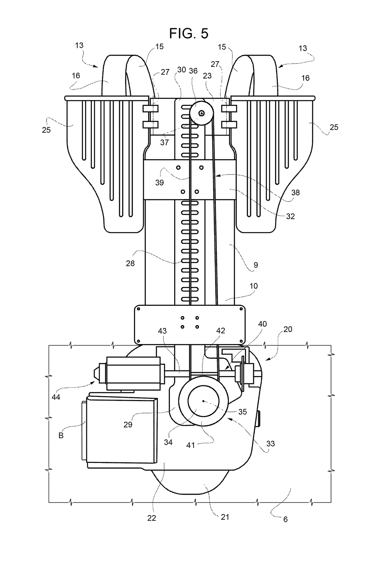
[0025]The supporting structure 1 further comprises a spinal prosthesis or a dorsal upright 9, which extends in a substantially vertical direction and has a lower end 10 coupled to the portion 6 of the lumbar band 4, preferably in a releasable manner and, conveniently, by snap action.

[0026]The supporting structure also comprises...


PUM


Abstract

A wearable supporting structure for supporting ballistic protections and / or military equipment has a band suitable to be wrapped around the waist or hips of a user; a dorsal upright having a lower end coupled to the band and extending, in use, upwards from the band; a vest for supporting ballistic protections and / or other military equipment, coupled to the dorsal upright and comprising two shoulder straps; and a unit connecting the shoulder straps to the band; the connecting unit being motorised to be able to continuously adjust the position in height of the shoulder straps with respect to the band.

Description

BACKGROUND[0001]Technical Field[0002]The present invention relates to a wearable supporting structure for supporting ballistic protections and / or military equipment.[0003]Description of the Related Art[0004]Both in the military and civilian fields, the need is felt to carry loads on the back or on the shoulders, however, without overloading the user's spinal column or creating localized stress.[0005]For this purpose, structures are known which have two shoulder straps that support the load and are connected to a lumbar band, which is wrapped around the waist or hips of the user, so as to shift at least part of the weight from the shoulders to the lumbar area of the user by means of said lumbar band.[0006]With specific reference to the military field, to which the following discussion will make explicit reference without thereby losing generality, the structure supports ballistic protections, which are rigid plates of considerable weight and thickness. In addition to this, the struct...

Claims


Application Information

Patent Timeline
Patent Type & Authority Patents(United States)
IPC IPC(8): A41H1/02A41D1/04A45F3/14F41H1/02A41D1/00F41H5/013A45F3/10A45F3/08A45F3/06A45F3/04
CPCF41H1/02A41D1/002A41D1/04A45F3/06A45F3/08A45F3/14F41H5/013A45F3/10A45F2003/146A45F2003/045A45F2003/144A45F3/047
Inventor CASTRATI, MAURIZIO
Owner MECH LAB
Why Eureka
Try Eureka