Perivalvular occlusion device and methods

a perivalvular occlusion and valve technology, applied in the field of perivalvular occlusion devices and methods, can solve problems such as occlusion of leakage channels, and achieve the effects of reducing the risk of occlusion

Active Publication Date: 2019-03-26
DRASLER WILLIAM JOSEPH
View PDF12 Cites 2 Cited by
  • Summary
  • Abstract
  • Description
  • Claims
  • Application Information

AI Technical Summary

Benefits of technology

[0006]The channel that forms the perivalvular leak has a generally undulating shape throughout the surface of the channel. The cross section is generally not formed as a perfect oval but instead has many undulation protrusions and cavities that can be formed from calcium deposits located along the native valve leaflets. Such undulation also extends along the axial length of the channel. The stent structure of a TAVR device or the sewing ring of a surgical valve can also form undulations in the channel shape that can protrude into the channel or form pockets and cavities that make up the surface of the perivalvular channel. The present invention is intended to extend into and around these cavities and protrusions to form a tight fit into the undulations that will prohibit migration of the occlusion device and will improve the ability of device to block blood flow through the channel.
[0020]In further yet another embodiment for the SE occlusion device, the SE stent can be contained within a balloon or positioned on the outside of a balloon that is filled with either saline or a curable polymer. The balloon can be formed from a noncompliant or semicompliant material that extends easily to cover the perimeter of the channel. The occlusion device is first released from the sheath and allowed to expand outwards into the channel. The balloon is then inflated with saline or polymer to force the balloon and covering into contact with the undulations of the channel and push the stent into intimate contact with all aspects of the channel. Then the balloon is released via a thread and screw mechanism, for example. A valve can be provided to prevent escape of the polymer or saline following expansion of the balloon.

Problems solved by technology

Alternately, in some embodiments the cover can be a fabric that is formed from a porous material that will eventually become occluded and thereby result in occlusion of the leak channel.

Method used


Image

  • Perivalvular occlusion device and methods
  • Perivalvular occlusion device and methods
  • Perivalvular occlusion device and methods

Examples


Embodiment Construction

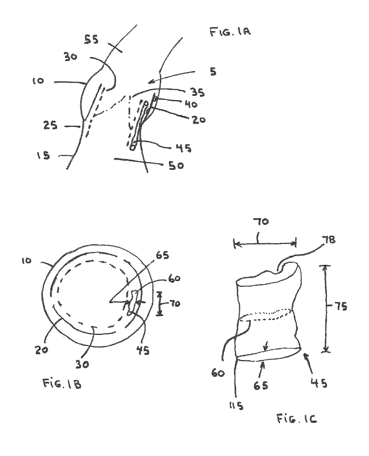
[0086]FIG. 1A shows the anatomy of the aortic root (5) showing the aortic sinus (10) joined to the left ventricle, LV (15). The native aortic valve leaflets (20) are attached to the annulus (25) and have been pushed to the side via a TAVR stented device (30) that contains TAVR replacement leaflets (35). Calcium nodules (40) located on the back surface of the native leaflets have created a channel (45) that travels between the TAVR stented device and the native leaflets. The channel (45) extends from the aortic sinus past the aortic annulus (25) and into the left ventricular outflow tract, LVOT (50). This channel (45) creates a perivalvular leak that allows retrograde passage of blood from the aorta (55) directly to the LV (15) during diastole.

[0087]Looking at a cross sectional view of the aortic sinus, as shown in FIG. 1B, one can see that the channel cross-section (60) has an oval or crescent-like shape that extends around a portion of the perimeter of the TAVR device. The channel ...


PUM


Abstract

An occlusion device intended for blocking perivalvular leak channels that are found following heart valve implantation between the heart valve and the surrounding tissue. The occlusion device has a stent and a covering that is attached to the stent surface. A blocking fabric extends across the lumen of the stent to block blood flow. The stent pattern and wall structure provide for small radius of curvature bends to fill narrow channels that cause the perivalvular leaks.

Description

CROSS REFERENCE TO RELATED APPLICATIONS[0001]This patent application makes reference to and thereby incorporates all information found in the provisional patent application numbered 62 / 283,688 entitled Perivalvular Occlusion Device and Methods, filed 8 Sep. 2015 by William J. Drasler.BACKGROUND OF THE INVENTION[0002]The implantation of Transcatheter Aortic Valve Replacement (TAVR) devices and Transcatheter Mitral Valve Replacement (TMVR) devices has provided significant opportunity for improved health for those patients that are too sick to undergo surgical valve replacement or those who are of significant age of which the trauma associated with surgical replacement does not merit the potential benefits of surgical replacement over transcatheter valve replacement. Although improvements are continuously being made in the TAVR and MTVR devices and their procedures, the presence of leakage of blood across the transcatheter valve in a retrograde direction has raised clinical concerns in...

Claims


Application Information

Patent Timeline
Patent Type & Authority Patents(United States)
IPC IPC(8): A61F2/24
CPCA61F2/246A61F2/2466A61F2250/0003A61F2210/0014
Inventor DRASLER, WILLIAM JOSEPH
Owner DRASLER WILLIAM JOSEPH
Why Eureka
Try Eureka