Multi-stage broadband directional coupler

a directional coupler and multi-stage technology, applied in the direction of coupling devices, electrical devices, waveguides, etc., can solve the problems of no longer being produced economically, limited coupling factor, and small distances

Active Publication Date: 2019-03-26
TELEFON AB LM ERICSSON (PUBL)
View PDF18 Cites 0 Cited by
  • Summary
  • Abstract
  • Description
  • Claims
  • Application Information

AI Technical Summary

Benefits of technology

[0024]In a preferred embodiment of the invention, it is further possible for the coupling distance, in particular between the coupling portions positioned closest together, to subsequently be able to be fine-tuned slightly by the possibility of inserting and/or fixing dielectric spacers (for example in the form of a plastics material plate etc.), which may be of small dimensions, between the coupling portions positioned closest together.
[0025]Also, ...

Problems solved by technology

For higher coupling levels, such as are required for a power splitter, these distances are often very small, or even so small that they can no longer be produced economically.
The main drawbacks of the directional couplers using coplanar line technology relate inter alia to the required minimum distances between the conductor paths coupled on the longitudinal faces and to the coupling factor, which is thus also limited.
Further, the coupling factor is highly tolerance-dependent (etching tolerances and fluctuations in the dielectric constant of the substrate ma...

Method used


Image

  • Multi-stage broadband directional coupler
  • Multi-stage broadband directional coupler
  • Multi-stage broadband directional coupler

Examples


Embodiment Construction

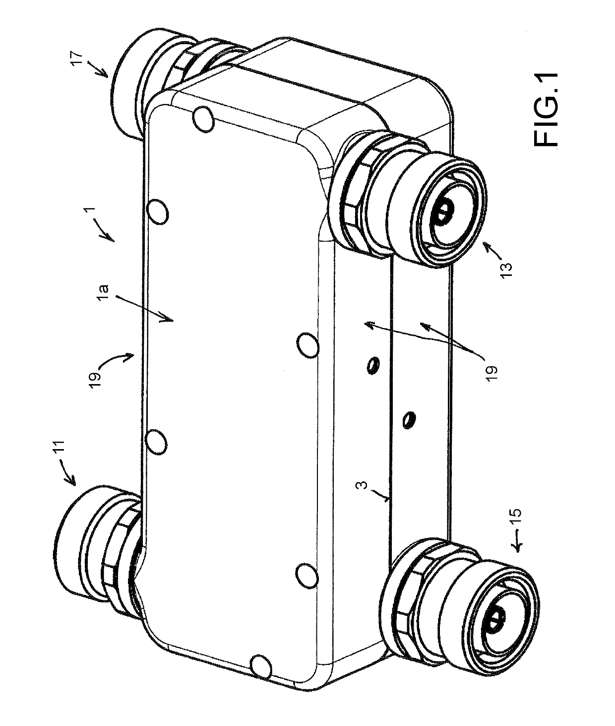
[0034]The drawings show the directional coupler according to the invention having a coupler housing 1, which in the embodiment shown comprises coupler housing halves 1a and 1b formed identically in terms of size.

[0035]In other words, the two coupler housing halves 1a, 1b are of the same length, the same width and the same height transverse to the separating plane 3 thereof.

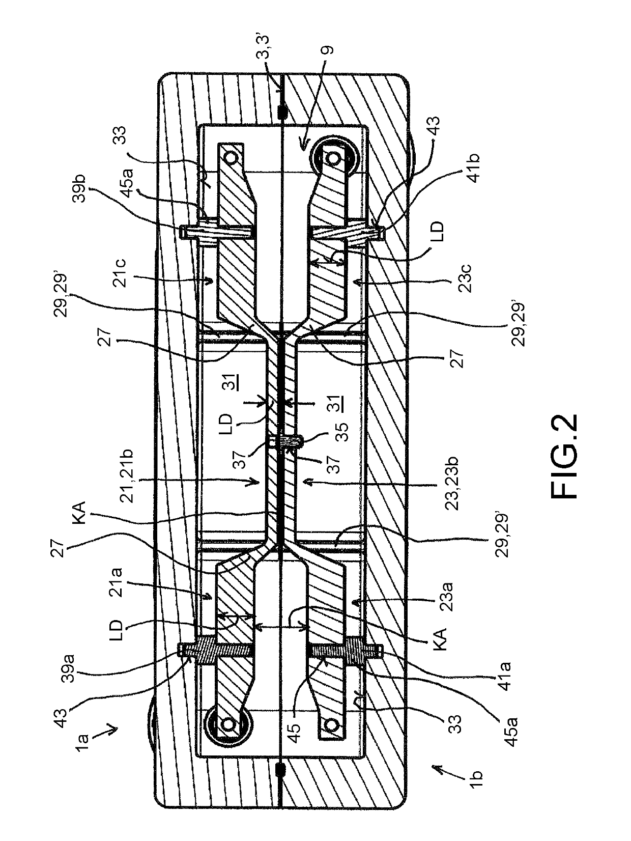
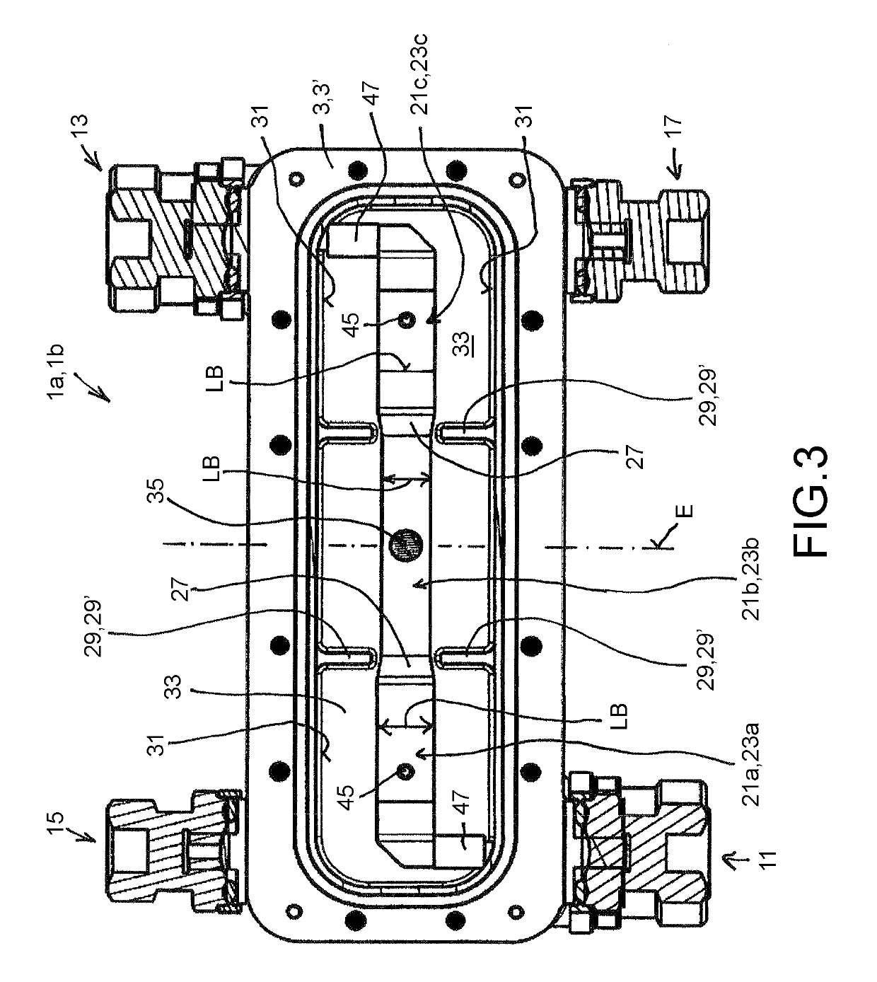
[0036]Two adjacent coupler housing halves 1a and 1b, visible from the opening faces 5 thereof, are formed identically (or formed substantially identically) and can be placed with the opening faces 5 thereof against one another by rotation through 180°, in such a way that the housing half contact planes 7, each positioned at the separating plane 3, of the two coupler housing halves 1a, 1b come to be positioned against one another, including the coupling path (discussed further below) provided in the housing interior 9.

[0037]Like any directional coupler, the directional coupler comprises at least three ports, but ge...


PUM


Abstract

An improved multi-stage broadband directional coupler with at least one line junction between two successive coupling sections has a) a change in the line thickness (LD) and/or b) a change in the line width (LB) and/or c) a change in the coupling distance (KA) between the adjacent coupling sections of the two coupling lines. An electrically conductive cover connected to the coupler housing is provided adjacent to the at least one line junction.

Description

CROSS-REFERENCE TO RELATED APPLICATIONS[0001]This application is the U.S. national phase of International Application No. PCT / EP2015 / 000451 filed 26 Feb. 2015, which designated the U.S. and claims priority to DE Patent Application No. 10 2014 004 007.0 filed 20 Mar. 2014, the entire contents of each of which are hereby incorporated by reference.STATEMENT REGARDING FEDERALLY SPONSORED RESEARCH OR DEVELOPMENT[0002]None.FIELD[0003]The invention relates to a multi-stage broadband directional coupler.[0004]In high-frequency systems, it is often necessary to split a signal, for example of a power P, into two signals in any given power split. In special cases, it may be desirable to split the power into 50% in each case. Hybrid ring couplers are often used for this purpose. Hybrid ring couplers of this type are known inter alia from Zinke Brunswig “Hochfrequenztechnik”, Springer-Verlag, 6th edition, 2000, in particular page 192.BACKGROUND AND SUMMARY[0005]These hybrid ring couplers are fre...

Claims


Application Information

Patent Timeline
IPC IPC(8): H01P5/18H01P5/08H01P3/08
CPCH01P5/183H01P5/187H01P5/085H01P5/18
Inventor WEISS, FRANK
Owner TELEFON AB LM ERICSSON (PUBL)
Why Eureka
Try Eureka