Multi-stage broadband directional coupler

A directional coupler and coupler technology, applied in the directions of waveguide-type devices, circuits, connecting devices, etc., can solve the problems of complex structure of directional couplers or power dividers, and achieve easy manufacturing and adjustment, low manufacturing, and realization cost. Effect

Active Publication Date: 2016-11-23
TELEFON AB LM ERICSSON (PUBL)
View PDF5 Cites 3 Cited by
  • Summary
  • Abstract
  • Description
  • Claims
  • Application Information

AI Technical Summary

Problems solved by technology

[0007] Furthermore, the main disadvantage of directional couplers in in-plane conducting technology is the required minimum distance between the conductor circuits coupled on the longitudinal sides and the coupling coefficient also defined for this purpose
[0010] However, directional couplers or power dividers are relatively complex in structure in coaxial conduction technology

Method used


Image

  • Multi-stage broadband directional coupler
  • Multi-stage broadband directional coupler
  • Multi-stage broadband directional coupler

Examples


Embodiment Construction

[0027] The multistage directional coupler shown in the figures is designed as a 3dB directional coupler, for example. However, the coupling sections can also be designed differently, so that power distributions other than 50 / 50 are also possible at any time.

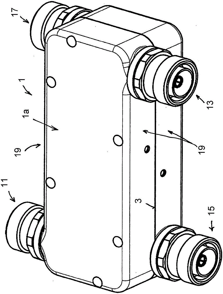
[0028] The drawing shows a directional coupler according to the invention with a coupler housing 1 which, in the exemplary embodiment shown, comprises coupler housing halves 1a and 1b of identical design in terms of dimensions.

[0029] In other words, the two coupler housing halves 1 a , 1 b have the same length, the same width and the same height transverse to their separating plane 3 .

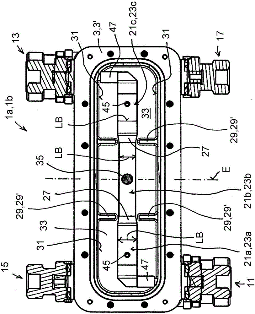
[0030] The two side-by-side coupler housing halves 1a and 1b, which are visible from their open sides 5, are identical (or substantially identical) and can be placed one above the other by rotating their open sides 5 by 180°, so that The housing half contact planes 7 of the two coupler housing halves 1 a , 1 b , each lying at the lev...


PUM


Abstract

An improved multi-stage broadband directional coupler is characterized, inter alia, by the following features: the at least one line junction (27) between two successive coupling sections (21a, 21b, 21c; 23a, 23b, 23c) has a) a change in the line thickness (LD) and / or b) a change in the line width (LB) and / or c) a change in the coupling distance (KA) between the adjacent coupling sections (21a, 21b, 21c, 23a, 23b, 23c) of the two coupling lines (21, 23), and an electrically conductive cover (29) connected to the coupler housing (1) is provided adjacent to the at least one line junction (27).

Description

technical field [0001] The invention relates to a multi-stage broadband directional coupler according to the preamble of claim 1 . Background technique [0002] In high-frequency devices it is often necessary to distribute a signal with power P, for example, to two signals with an arbitrary power distribution. In special cases it may be desirable to distribute the power by 50% in each case. Ring couplers are often used for this. Ring couplers of this type are also known from Zinke Brunswig "High Frequency Technology" (Springer Verlag, 6th edition, 2000) and see p. 192 there more precisely. [0003] These ring couplers are commonly used in microstrip line conduction technology. [0004] In addition, however, high-frequency couplers are also known, in which the degree of coupling is usually adjusted via lines coupled on the end side or on the longitudinal side. For higher degrees of coupling, such as are necessary for power dividers, these distances are often very small or...

Claims


Application Information

Patent Timeline
Patent Type & Authority Applications(China)
IPC IPC(8): H01P5/18
CPCH01P5/085H01P5/187H01P5/18H01P5/183
Inventor F·魏斯
Owner TELEFON AB LM ERICSSON (PUBL)
Why Eureka
Try Eureka