Optical system for small-bore endoscope

An optical system and endoscope technology, applied in the field of medical devices, can solve the problems of short range of clear imaging object distance, discount of endoscope detection effect, inconvenient inspection, etc., achieving low tolerance sensitivity, small change in working focal length, and improved wildcard effect

Pending Publication Date: 2018-04-06
ZHONGSHAN ZHONGYING OPTICAL
View PDF0 Cites 3 Cited by
  • Summary
  • Abstract
  • Description
  • Claims
  • Application Information

AI Technical Summary

Problems solved by technology

At present, most endoscopes have large calibers, and the process of entering the human body is relatively painful, and it is not convenient to inspect the lesion with narrow channels; The range is very short, which greatly reduces the detection effect of the endoscope

Method used


Image

  • Optical system for small-bore endoscope
  • Optical system for small-bore endoscope
  • Optical system for small-bore endoscope

Examples


Embodiment 1

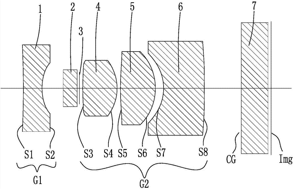
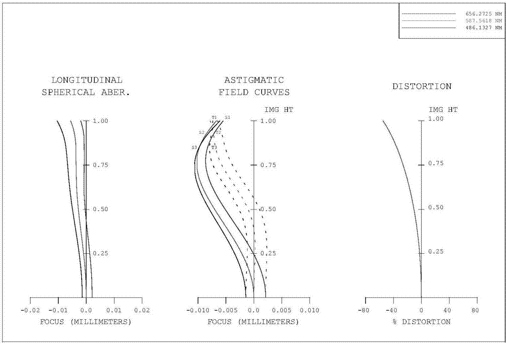
[0116] The structure of the endoscope optical system of Embodiment 1 of the present invention is shown in figure 2 In , the aberration curve of the endoscope optical system of Embodiment 1 of the present invention in air is shown in image 3 , the aberration curve in the human body is expressed in Figure 4 middle.

[0117] Table 1 is the lens data table of Embodiment 1 of the endoscope optical system.

[0118]

[0119]

[0120] Table 1

[0121] Table 2 shows the range of the ratio of the aspheric sagittal height to the radius R of the first lens 1 and the second lens 4 in Embodiment 1 of the endoscope optical system.

[0122]

[0123] Table 2

[0124] Table 3 shows the range of the ratio of the aspheric sagittal height to the radius R of the third lens 5 and the fourth lens 6 in Embodiment 1 of the endoscopic optical system.

[0125]

[0126] table 3

Embodiment 2

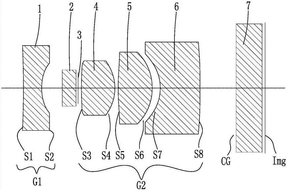
[0128] The structure of the endoscope optical system of Embodiment 2 of the present invention is shown in Figure 5 In , the aberration curve of the endoscope optical system of Example 2 of the present invention in air is shown in Image 6 , the aberration curve in the human body is expressed in Figure 7 middle.

[0129] Table 4 is the lens data table of Embodiment 2 of the endoscope optical system.

[0130]

[0131]

[0132] Table 4

[0133] Table 5 shows the range of the ratio of the aspheric sagittal height to the radius R of the first lens 1 and the second lens 4 of the second embodiment of the endoscopic optical system.

[0134]

[0135]

[0136] table 5

[0137] Table 6 shows the ratio range of the aspherical sagittal height to the radius R of the third lens 5 and the fourth lens 6 of the second embodiment of the endoscope optical system.

[0138]

[0139] Table 6

Embodiment 3

[0141] The structure of the endoscope optical system of Embodiment 3 of the present invention is shown in Figure 8 In , the aberration curve of the endoscope optical system of Example 3 of the present invention in air is shown in Figure 9 , the aberration curve in the human body is expressed in Figure 10 middle.

[0142] Table 7 is the lens data table of Embodiment 3 of the endoscope optical system.

[0143]

[0144] Table 7

[0145] Table 8 shows the range of the ratio of the aspheric sagittal height to the radius R of the first lens 1 and the second lens 4 of the third embodiment of the endoscopic optical system.

[0146]

[0147] Table 8

[0148] Table 9 shows the range of the ratio of the aspheric sagittal height to the radius R of the third lens 5 and the fourth lens 6 in Embodiment 3 of the endoscope optical system.

[0149]

[0150]

[0151] Table 9


PUM


Abstract

The invention relates to a small-diameter endoscope optical system, which is sequentially provided with a first lens (1), an optical filter (2), a fixed diaphragm (3), a second lens (4), The third lens (5), the fourth lens (6), the chip protection glass (7), and the endoscope optical system satisfy the relationship: 1<|fb / f|<1.8; 0.7<|fa / f|<0.9;| f‑fw|<0.008; 0.69<|R1+R2| / |R1‑R2|<1, the endoscope optical system of the present invention has the same optimal imaging object distance in the human body and in the air.

Description

【Technical field】 [0001] The patent of the present invention relates to a medical device, especially a small-diameter endoscope optical system. 【Background technique】 [0002] With the rapid development of science and technology, the medical industry has also made great progress, and the technology of using endoscope for inspection and using endoscope for minimally invasive surgery has gradually developed and matured. As an optical instrument, the endoscope can enter the body through the natural channel of the human body to image the lesion, and can directly observe the lesion in the organ. At present, most endoscopes have large calibers, and the process of entering the human body is relatively painful, and it is not convenient to inspect the lesion with narrow channels; The range is very short, which greatly reduces the detection effect of the endoscope [0003] Due to the above-mentioned problems, it is necessary to propose a solution, and the present invention is made u...

Claims


Application Information

Patent Timeline
Patent Type & Authority Applications(China)
IPC IPC(8): A61B1/00G02B23/24G02B13/00
CPCA61B1/00163G02B13/00G02B23/243
Inventor 范俊辉朱佳巍习宇李璇牛明宇
Owner ZHONGSHAN ZHONGYING OPTICAL
Why Eureka
Try Eureka