
Image processing apparatus, optical apparatus, and image processing method

a technology of image processing and optical equipment, applied in the field of image processing equipment, optical equipment, image processing methods, can solve the problems of large amount of video delay in outputting an image, inability to process a divided image including a large overlap region within the predetermined time,

Active Publication Date: 2019-04-09
CANON KK
View PDF12 Cites 0 Cited by
  • Summary
  • Abstract
  • Description
  • Claims
  • Application Information

AI Technical Summary

Benefits of technology

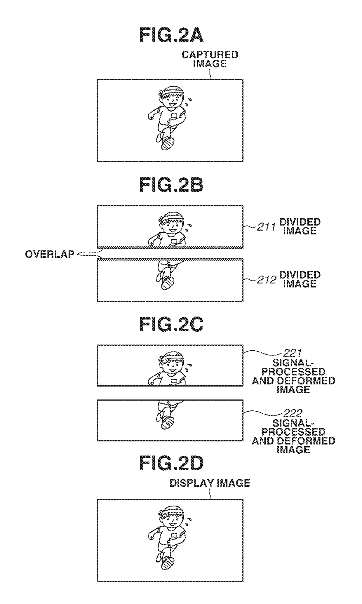
[0015]Embodiments of the present invention provide an imaging apparatus capable of correcting shaking occurring in a captured image due to movement of the imaging apparatus with a minimum amount of video delay within the range of a predetermined image processing ability in a case where an input image is divided into divided images and a plurality of image processing processors performs image processing on the divided images.

Problems solved by technology

In such an apparatus, in a case where the use of only one image processing processor (image processing large-scale integration (LSI)) leads to lack of image processing ability, a technique is employed which cuts out a plurality of divided images from one input image and concurrently performs image processing on the plurality of divided images with the use of a plurality of image processing processors.
However, satisfying both the technique which divides an input image and performs image processing with a plurality of image processing processors and the technique which corrects, for example, camera shake by changing readout positions on an image memory has not been conceived so far.
In that case, if each image processing processor has only about half of the processing ability, it is impossible to process a divided image including a large overlap region within the predetermined time.
In that case, since a readout operation needs to be performed after pasting is performed by the image memory, the amount of video delay in outputting an image would become large.

Method used


Image

  • Image processing apparatus, optical apparatus, and image processing method
  • Image processing apparatus, optical apparatus, and image processing method
  • Image processing apparatus, optical apparatus, and image processing method

Examples


Embodiment Construction

(Block Diagram of Imaging Apparatus)

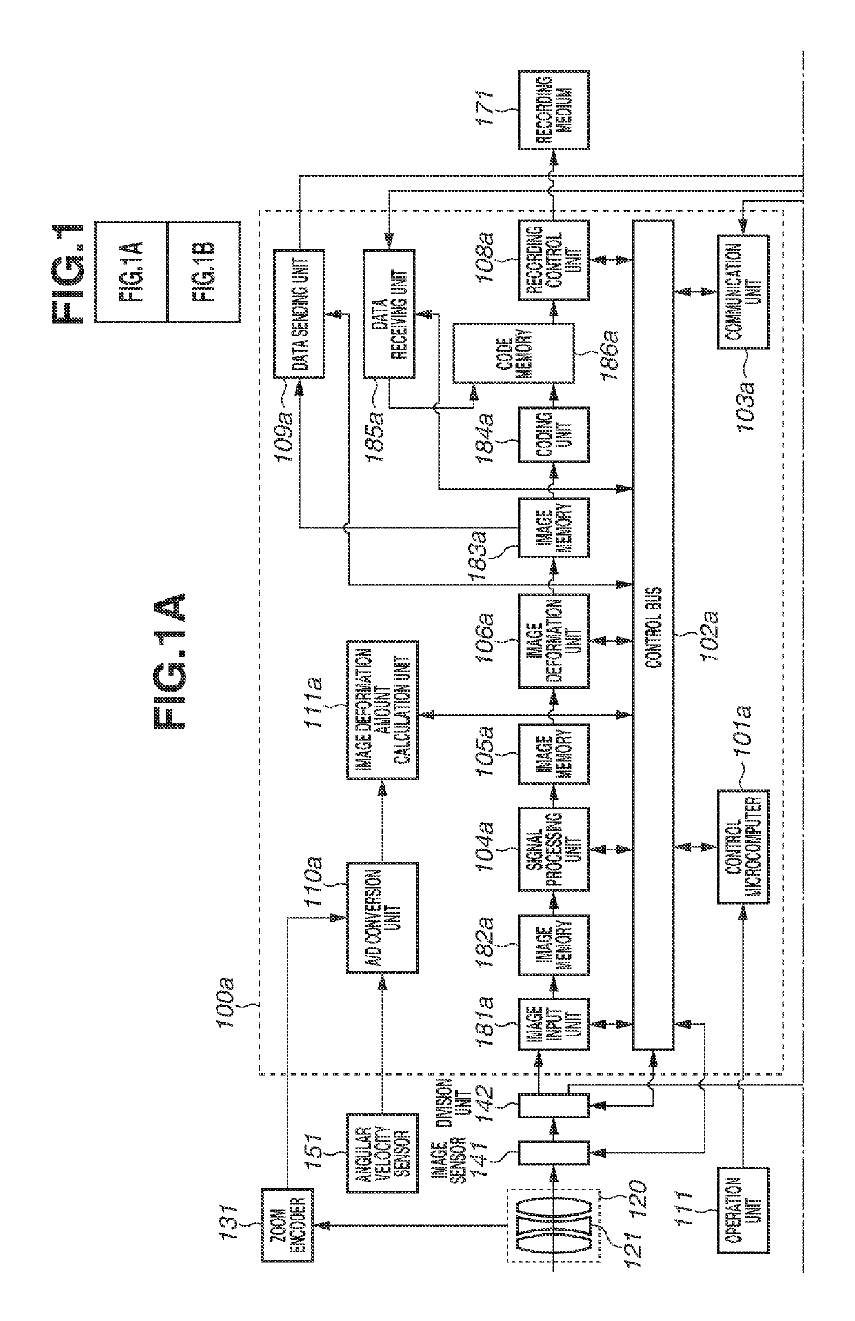
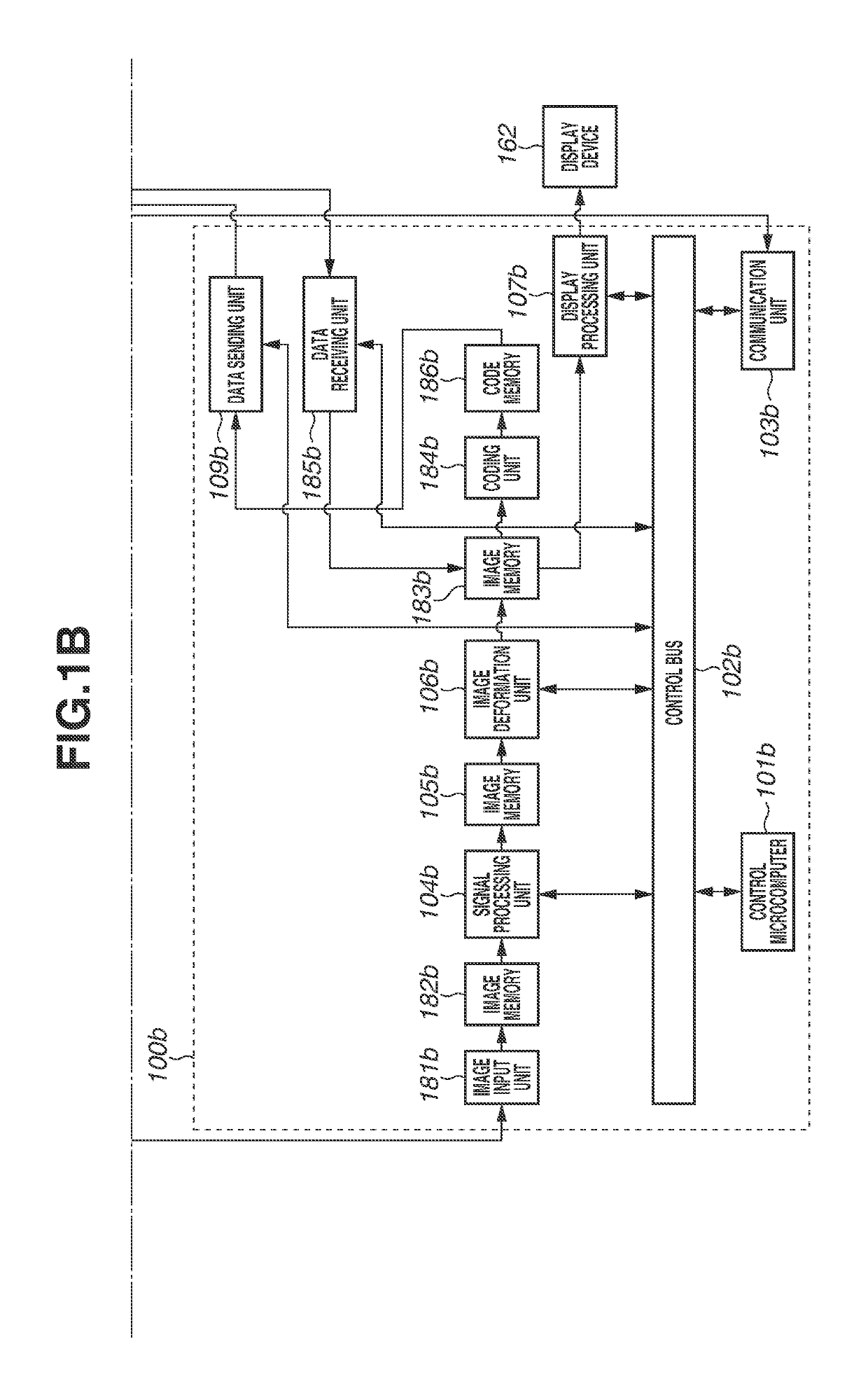
[0034]A configuration (block diagram) of an imaging apparatus serving as an optical apparatus according to a first exemplary embodiment of the invention is described with reference to FIG. 1, which is composed of FIGS. 1A and 1B.

[0035]A first image processing processor 100a and a second image processing processor 100b each process input divided image data and output the processed image data.

[0036]An operation unit 111 is configured with, for example, recording start / end buttons and a touch panel mounted on the exterior portion of an imaging apparatus body, and transmits an operation performed by the operator to the first image processing processor 100a.

[0037]An imaging optical system 120 forms a subject image on the imaging plane of an image sensor 141 via an optical lens group such as a variable magnification optical system 121.

[0038]A zoom encoder 131 detects the position of the variable magnification optical system 121 (zoom position), and out...


PUM


Abstract

An image processing apparatus includes a division unit configured to divide one frame image into a plurality of divided images, a plurality of image processing units configured to respectively process the plurality of divided images, and a combining unit configured to combine the divided images respectively subjected to image deformation processing by the plurality of image processing units, wherein the division unit changes an amount of overlap between the plurality of divided images according to a deformation amount of the image deformation processing performed on the divided image calculated by the image processing unit.

Description

BACKGROUND OF THE INVENTIONField of the Invention[0001]Aspects of the present invention generally relate to an image processing apparatus which divides an input image and performs image processing on the divided images. The image processing apparatus is applied to an optical apparatus, such as a digital still camera and a digital video camera.Description of the Related Art[0002]In recent years, cameras having such a higher resolution as to be compatible with 4K (a resolution of 3840×2160 pixels) have been developed.[0003]In such an apparatus, in a case where the use of only one image processing processor (image processing large-scale integration (LSI)) leads to lack of image processing ability, a technique is employed which cuts out a plurality of divided images from one input image and concurrently performs image processing on the plurality of divided images with the use of a plurality of image processing processors.[0004]In a case where an input image is divided into a plurality o...

Claims


Application Information

Patent Timeline
Patent Type & Authority Patents(United States)
IPC IPC(8): H04N5/232H04N5/235
CPCH04N5/23264H04N5/235H04N5/23277H04N5/23254H04N5/23229H04N23/80H04N23/6811H04N23/6845H04N23/682H04N23/70
Inventor MATSUYAMA, ICHIRO
Owner CANON KK
Learn More