
Image-shake correction apparatus and control method thereof

a technology of image shake and correction apparatus, which is applied in the field of image shake correction apparatus, can solve the problems of increasing the amount of distortion generated depending on the field angle, and difficulty in providing optical image stabilizing effect in all regions

Active Publication Date: 2017-03-28
CANON KK
View PDF5 Cites 0 Cited by
  • Summary
  • Abstract
  • Description
  • Claims
  • Application Information

AI Technical Summary

Benefits of technology

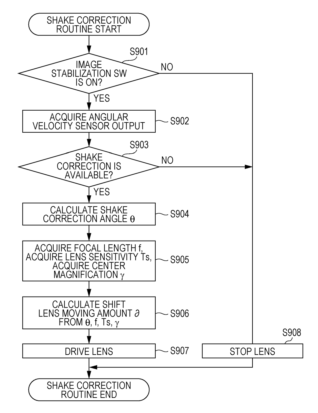
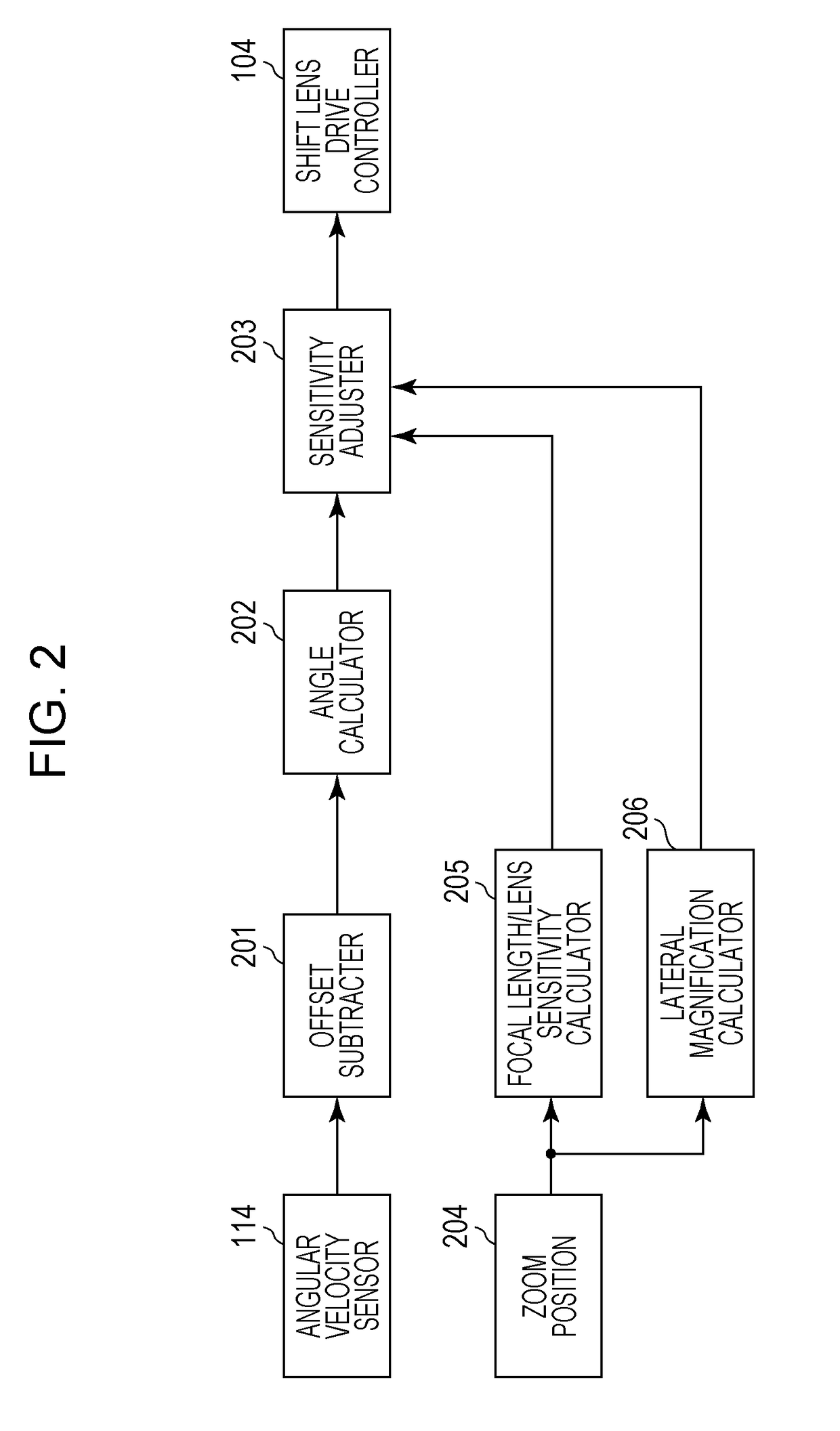
[0025]According to an aspect of the invention, there is provided an image-shake correction apparatus including a calculating unit configured to calculate a shake correction amount on the basis of an output of a shake detecting unit; and a control unit configured to control an image-shake correction unit configured to correct image shake in accordance with the shake correction amount. If distortion is generated such that a screen peripheral portion of an image pickup screen of an image pickup element is reduced as compared with a screen center portion of the image pickup screen and if distortion is generated such that the screen center portion is reduced as compared with the screen peripheral portion, image-shake correction effect in the screen center portion is higher than image-shake correction effect in the screen peripheral portion.

Problems solved by technology

With such a zoom lens, the amount of distortion generated depending on the field angle is increased.
However, in an optical image-stabilization mechanism built in an image pickup optical system, optical image stabilization has to be performed in image pickup optical characteristics having optical distortion remaining therein.
Hence, it is difficult to properly provide optical image stabilizing effect in all region of an image.

Method used


Image

  • Image-shake correction apparatus and control method thereof
  • Image-shake correction apparatus and control method thereof
  • Image-shake correction apparatus and control method thereof

Examples


first embodiment

[0038]An embodiment of the invention is described below with reference to the drawings.

Description for Block Diagram of Image Pickup Device

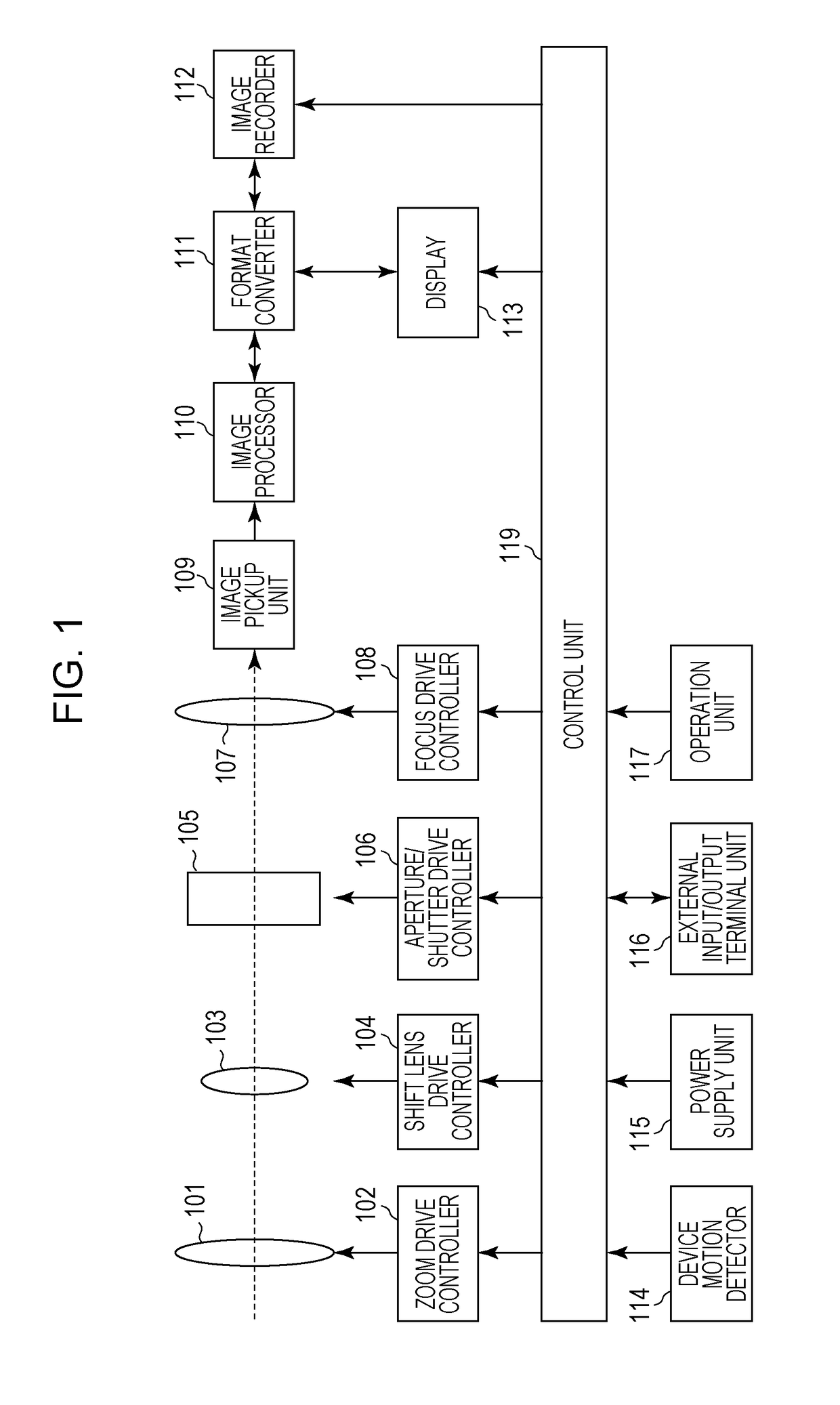
[0039]FIG. 1 is a block diagram showing a configuration of an image pickup device having an image-shake correction function according to this embodiment of the invention.

[0040]In FIG. 1, a zoom unit 101 includes a zoom lens that changes the magnification. A zoom drive controller 102 controls driving of the zoom unit 101.

[0041]A shift lens 103 serves as a shake correction optical system that can change the position thereof in a plane substantially perpendicular to the optical axis. A shift lens drive controller 104 controls driving of the shift lens 103. An aperture / shutter unit 105 is also provided. An aperture / shutter drive controller 106 controls driving of the aperture / shutter unit 105.

[0042]A focus unit 107 includes a lens for focus adjustment. A focus drive controller 108 controls driving of the focus unit 107.

[0043]In an image pickup unit 1...

second embodiment

[0106]According to the first embodiment, in many cases, the method of optimizing the image-shake correction effect (image stabilization effect) in a portion near the image center at which the resolution is emphasized the most has been described.

[0107]However, in some photographing scenes, there is a situation in which the resolution is emphasized not at the image center, but at a position separated from the center of a photographed image. For example, when a person is photographed as a main object, the person may not be always photographed while located in a portion near the center. Other object may be in the same situation.

[0108]For example, as shown in FIG. 5A, when the face of a person that is a main object is located in a portion near the center of an image to be photographed, if it is desirable to optimize the image stabilization effect in the portion near the face, the image stabilization control may be performed with regard to the lateral magnification in the portion near the...

third embodiment

[0148]In the above-described second embodiment, the method of optimizing the image stabilization effect at the object position has been described.

[0149]However, for example, when a face is detected as a main object and it is desired to obtain proper image stabilization effect for the entire region of the face, image-shake correction effect (image stabilization effect) may vary in the entire face region depending on the size of the face even if the object center position is the same.

[0150]For example, in FIGS. 8A and 8B, the center positions of the faces of persons being main objects are located at the center positions in images; however, the sizes of the faces in the images are different.

[0151]In FIG. 8A, the face with the size is arranged in a portion near the image center, optimal image stabilization effect can be obtained by the method described according to the second embodiment of setting the correction amount in accordance with the lateral magnification in the portion near the...


PUM


Abstract

In an image-shake correction apparatus, if distortion is generated such that a screen peripheral portion of an image pickup screen of an image pickup element is reduced as compared with a screen center portion of the image pickup screen and if distortion is generated such that the screen center portion is reduced as compared with the screen peripheral portion, image-shake correction effect in the screen center portion is higher than image-shake correction effect in the screen peripheral portion.

Description

BACKGROUND OF THE INVENTION[0001]Field of the Invention[0002]The present invention relates to an image-shake correction apparatus having a function of correcting shake caused by camera shake or vibration, and also relates to a control method of the image-shake correction apparatus.[0003]Description of the Related Art[0004]In recent years, a zoom lens used in an image pickup device such as a compact digital camera may be a super wide-angle zoom lens. With such a zoom lens, the amount of distortion generated depending on the field angle is increased.[0005]When optical design is made for a photographing lens unit, correction on distortion by the photographing lens unit may be reduced for simplifying optical design, and the distortion may be electronically corrected by digital image processing.[0006]Also, a recent camera is equipped with an image-stabilization control device that prevents image shake due to camera shake etc. The image-stabilization control device is briefly described he...

Claims


Application Information

Patent Timeline
Patent Type & Authority Patents(United States)
IPC IPC(8): H04N5/217H04N5/232G06T5/00H04N5/235
CPCH04N5/23254G06T5/006H04N5/2176H04N5/2328H04N5/23219H04N5/23258H04N5/235H04N23/611H04N23/6811H04N23/685H04N23/6812H04N23/70H04N23/682H04N25/63
Inventor WAKAMATSU, NOBUSHIGE
Owner CANON KK
Learn More