
Imaging device, imaging method and imaging device control program

a technology of imaging devices and control programs, applied in image enhancement, printers, instruments, etc., can solve problems such as inability to sufficiently suppress shakes, limitation of the exposure time of imaging elements, and shakes that occur

Active Publication Date: 2020-05-19
FUJIFILM CORP
View PDF14 Cites 1 Cited by
  • Summary
  • Abstract
  • Description
  • Claims
  • Application Information

AI Technical Summary

Benefits of technology

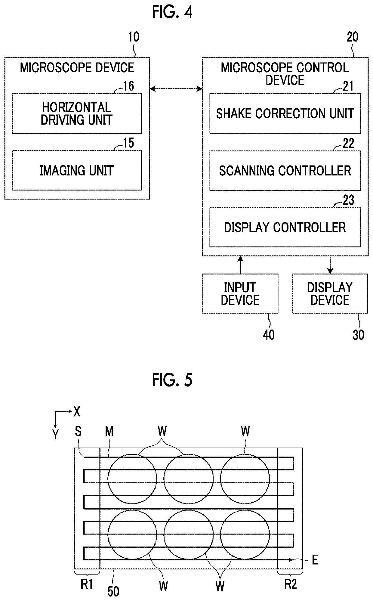
[0009]The present invention is contrived in view of the above problem, and an object thereof is to provide an imaging device, an imaging method and a non-transitory computer readable recording medium storing an imaging device control program that make it possible to perform high-speed image capture of an observation target such as a cell, and to correct a shake caused by the movement of a stage or the like appropriately and simply.
[0023]Shake correction for correcting a shake caused by movement of at least one of the stage or the imaging optical system is performed on the image signal which is Output from the imaging unit, and a correction filter used in the shake correction is switched in accordance with a movement direction of the at least one in the main scanning direction. In this manner, the shake correction is performed using the correction filter, and the correction filter is switched in accordance with the movement direction, whereby it is possible to perform high-speed image capture of an observation target such as a cell, and to correct a shake caused by the movement of a stage or the like appropriately and simply.

Problems solved by technology

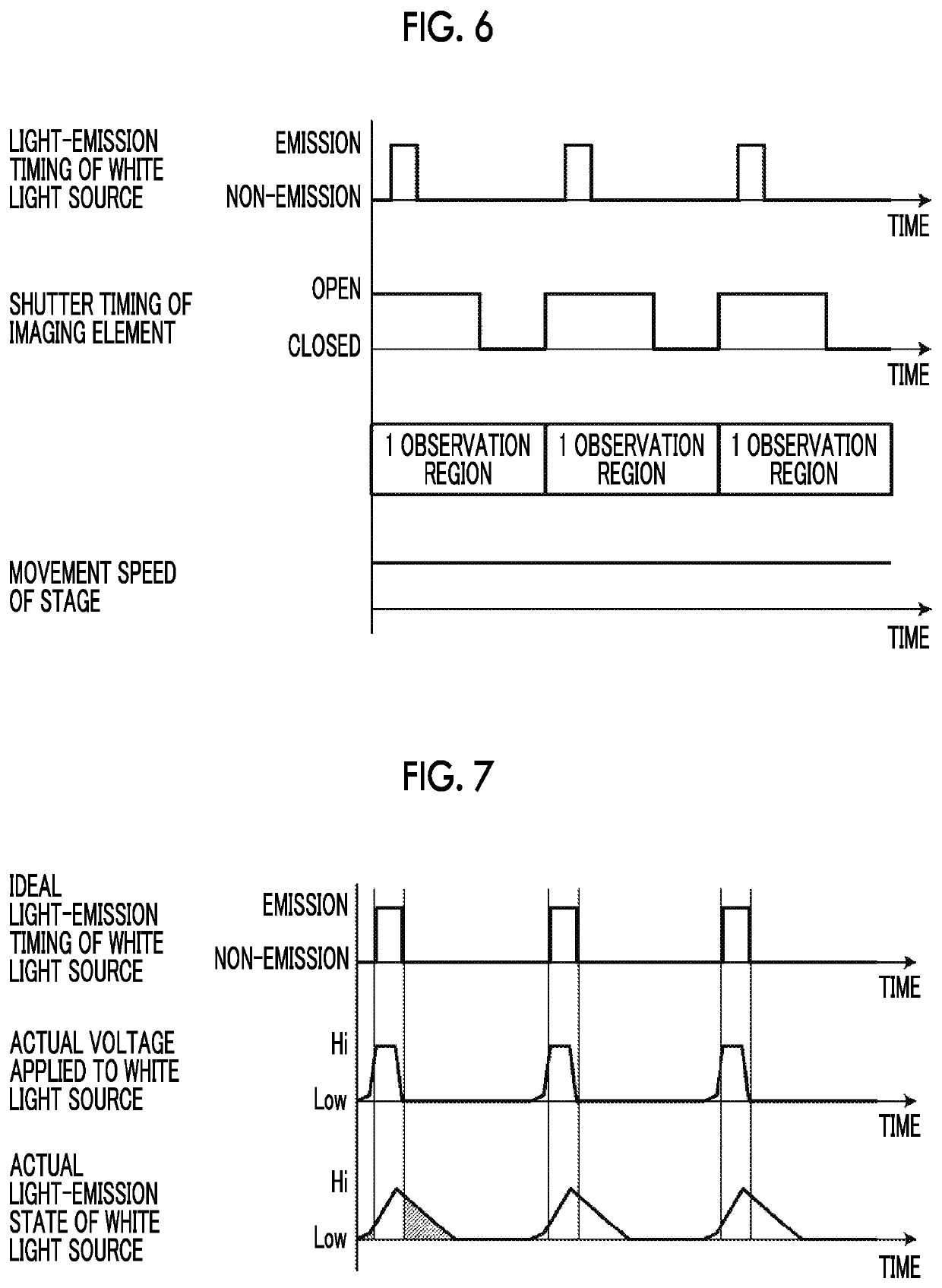
However, for example, in a case where an observation region is scanned by moving a stage on which a culture vessel is placed, high-speed image capture can be performed by moving the stage at high speed, but in a case where the exposure time of an imaging element that captures an image of an observation target is not appropriate, a shake occurs in the captured image.
The capability to simply control the exposure time of an imaging element for short period of time makes it possible to suppress a shake of an image, but there is a limitation on control of the exposure time of an imaging element, and thus it is not possible to sufficiently suppress a shake.
Therefore, the performing of the same shake correction on images for each observation region does not make it possible to appropriately correct a shake.

Method used


Image

  • Imaging device, imaging method and imaging device control program
  • Imaging device, imaging method and imaging device control program
  • Imaging device, imaging method and imaging device control program

Examples


Embodiment Construction

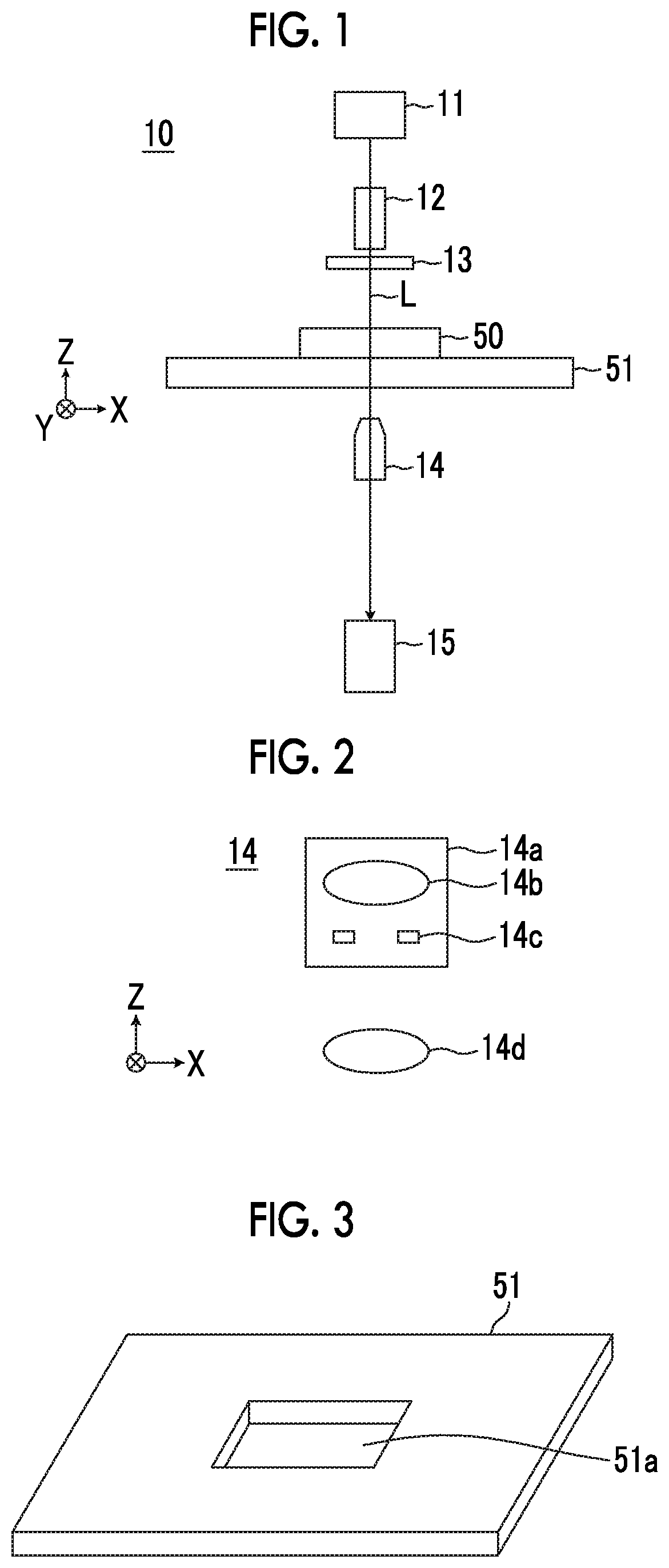
[0037]Hereinafter, a microscope imaging system using an embodiment of an imaging device, an imaging method and an imaging device control program of the present invention will be described in detail with reference to the accompanying drawings. FIG. 1 is a block diagram illustrating a schematic configuration of a microscope device 10 in a microscope imaging system of the present embodiment.

[0038]The microscope device 10 is configured to capture a phase difference image of a cultured cell which is an observation target. Specifically, as shown in FIG. 1, the microscope device 10 comprises a white light source 11 that emits white light, a capacitor lens 12, a slit plate 13, an imaging optical system 14, and an imaging unit 15.

[0039]The white light source 11 is a strobe light source that intermittently emits white light. The white light source 11 emits white light intermittently in accordance with the shutter timing of the imaging unit 15, and a single light-emission period is approximate...


PUM

PropertyMeasurementUnit
exposure timeaaaaaaaaaa
movement speedaaaaaaaaaa
speedaaaaaaaaaa

Abstract

Provided are an imaging device that make it possible to perform high-speed image capture of an observation target such as a cell, and to correct a shake caused by the movement of a stage or the like appropriately and simply. The imaging device includes a stage on which a vessel having an observation target received therein is installed, an imaging optical system that forms an image of the observation target, a horizontal driving unit that moves the stage in a main scanning direction and a sub-scanning direction orthogonal to the main scanning direction, and moves the stage forward and backward in the main scanning direction, an imaging unit that receives the image formed by the imaging optical system, and outputs an image signal of the observation target, and a shake correction unit that performs shake correction for correcting a shake caused by movement of the stage on the image signal.

Description

CROSS-REFERENCE TO RELATED APPLICATIONS[0001]This application is a Continuation of PCT International Application No. PCT / JP2017 / 008465 filed on Mar. 3, 2017, which claims priority wider 35 U.S.C § 119(a) to Japanese Patent Application No. 2016-093615 filed on May 9, 2016. Each of the above application(s) is hereby expressly incorporated by reference, in its entirety, into the present application.BACKGROUND OF THE INVENTION1. Field of the Invention[0002]The present invention relates to an imaging device, a imaging method and a non-transitory computer readable recording medium storing an imaging device control program for observing an image of the entire observation target by relatively moving a stage on which a vessel having an observation target received therein is installed and an imaging optical system that forms an image of an observation target.2. Description of the Related Art[0003]Hitherto, there is proposed a method of determining a differentiated state or the like of a cell ...

Claims


Application Information

Patent Timeline
Patent Type & Authority Patents(United States)
IPC IPC(8): H04N5/232G02B27/64G01N21/01G01N21/17H04N5/235G01N21/41G02B21/14G02B21/36G02B21/26G06T5/00H04N5/225G03B5/00
CPCG02B21/14G01N21/01H04N5/2329G01N21/17H04N5/23267H04N5/232H04N5/2354G01N21/41G02B21/26G06T5/003H04N5/225G02B21/367G02B27/646G03B5/00G06T2207/20201G06T2207/10056H04N23/672H04N23/00G02B21/36G01N2201/127H04N23/683H04N23/74H04N23/689
Inventor WAKUI, TAKASHI
Owner FUJIFILM CORP
Learn More