Vehicle lamp device

a technology for vehicle lamps and lamps, which is applied to vehicle components, lighting and heating apparatus, lighting apparatus, etc., can solve the problems that the headlamps with the combined system of high and low beams are difficult to design under the single lens structure, and achieve the effect of increasing the concentration of light and reducing the overall volume of vehicle lamps

Active Publication Date: 2019-04-16
CHIAN YIH OPTOTECH CO LTD
View PDF9 Cites 6 Cited by
  • Summary
  • Abstract
  • Description
  • Claims
  • Application Information

AI Technical Summary

Benefits of technology

[0005]With regard to overcoming the deficiency of the conventional technology, a vehicle lamp of the present disclosure is provided for increasing the concentration of light and reducing the overall volume of the vehicle lamp.
[0009]Therefore, the overall volume of the vehicle lamp can be reduced and the efficiency of light concentration can be increased by matching the feature of “both of the first carrier surface and the second carrier surface face toward an upward direction above a horizontal plane” of the vehicle lamp of the present disclosure.

Problems solved by technology

However, the headlamp with the combined system of high and low beam is difficult to be designed under the single lens structure because that the light emitting type of light-emitting diode (LED) is uniform surface light source without high light intensity area.
As a result, there is an important issue to overcome the aforementioned defects for a person of ordinary skill in the art, by performing a switchable function of high and low beams under LED light source and the single lens structure.

Method used


Image

  • Vehicle lamp device
  • Vehicle lamp device
  • Vehicle lamp device

Examples


first embodiment

[0052][First Embodiment]

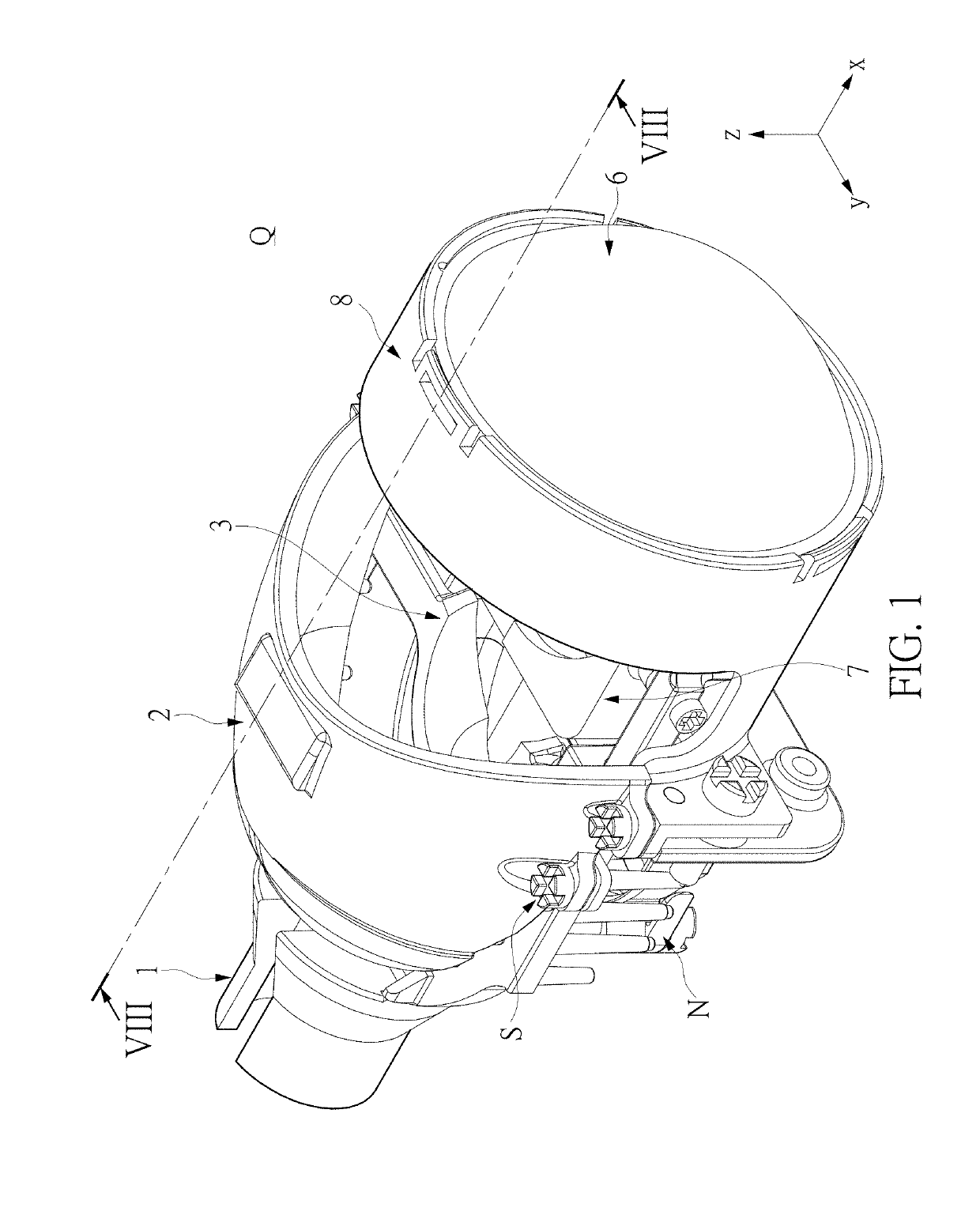
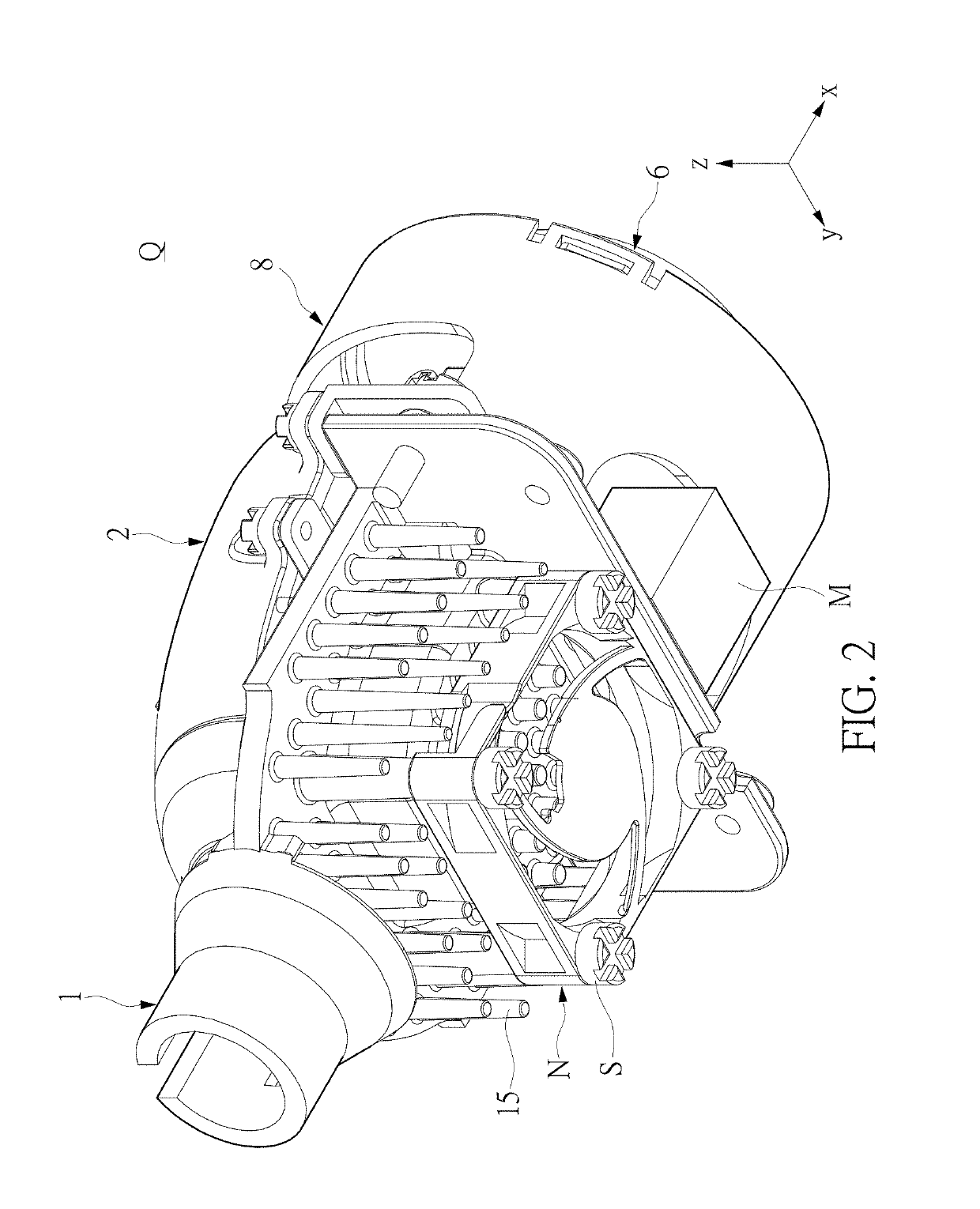
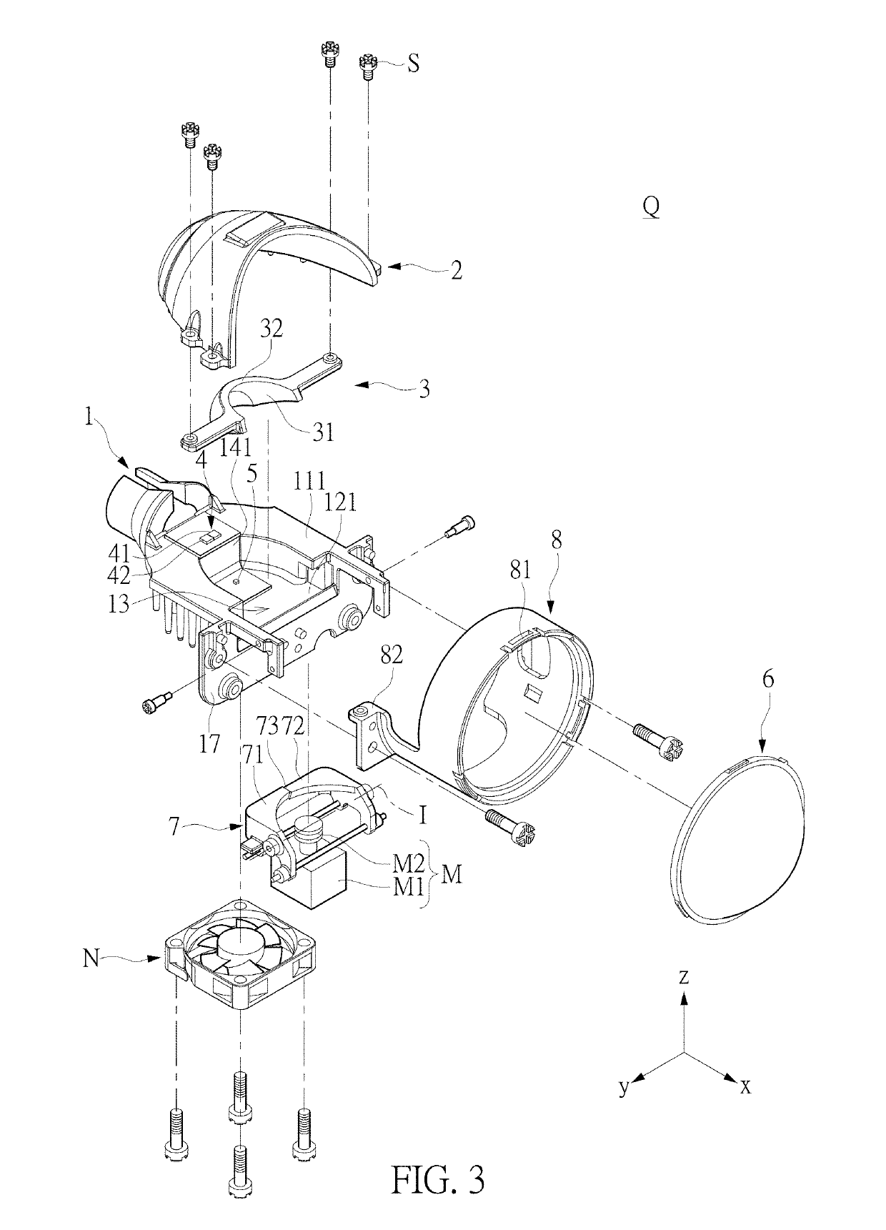
[0053]First, reference is made to FIG. 1 to FIG. 4 and FIG. 8. FIG. 1 to FIG. 4 are two perspective views and two exploded views of the vehicle light Q according to the first embodiment of the present disclosure. FIG. 8 is schematic view showing the main construction of the vehicle light Q under a high beam mode of operation. The present disclosure provides a vehicle lamp Q, which includes a base 1, a first reflection structure 2, a second reflection structure 3, a first light emitting structure 4, a second light emitting structure 5, a lens structure 6, and a shielding structure 7. For example, each of the first reflection structure 2 and the second reflection structure 3 is composed of multiple curved surfaces having different curvatures or a single curved surface; that is to say, the reflection structure can be composed of the curved surfaces based on the ellipsoid. In addition, the first reflection structure 2 and the second reflection structure 3 are dis...

second embodiment

[0079][Second Embodiment]

[0080]First, please refer to FIG. 19 to FIG. 24, a vehicle lamp is provided in the second embodiment. Compared FIG. 23 with FIG. 6, the main differences between the first embodiment and the second embodiment is as follows: the base 1 further includes a light beam modulator 9 in the second embodiment, and the shielding structure 7 can have another shape distinguished from the aforementioned implement for cooperating with the configuration of the light beam modulator 9 and the base 1. In addition, the shielding structure 7 further includes a reflection part 76, and the first reflection structure 2 further includes reflection board 24. The efficiency of light concentration can be increased by obliquely disposing the second carrier surface 121 of the vehicle lamp Q. Meanwhile, a part of the light is further reflected onto the central position of the generated light pattern through the disposition of the light beam modulator 9, so as to increase the efficiency of...


PUM


Abstract

A vehicle lamp is provided. The vehicle lamp includes a base, a first reflection structure, a second reflection structure, a first light emitting structure, a second light emitting structure, and a lens structure. The first reflection structure and second reflection structure are disposed on the base. The first reflection structure includes at least one first focal point and at least one second focal point. The second reflection structure includes a first focal point and a second focal point. The first light emitting structure and the second light emitting structure are disposed on the base. The lens structure includes a lens optical axis and a lens focal point.

Description

FIELD OF THE INVENTION[0001]The present disclosure relates to a vehicle lamp, and in particular to a vehicle lamp having the function of switching between high and low beam modes of operation.BACKGROUND OF THE INVENTION[0002]In the conventional design of the vehicle lamp, the demand and regulation for high beam and low beam are different. High beam requires concentrated light to achieve the purpose of long-distance illumination, but low beam requires diffused light to provide a wide viewing field in the close range. Accordingly, the designs of high beam and low beam are usually separated in the concept for designing the vehicle lamp. That is to say, each of high beam and low beam has specially adapted lamp cup. For instance, Taiwan Patent Publication No. M353845 discloses an headlight structure for driving illumination, in which the automobile light structure has the function of switching between high and low beam modes by individually independent high and low beam modules.[0003]Gen...

Claims


Application Information

Patent Timeline
Patent Type & Authority Patents(United States)
IPC IPC(8): F21V29/67F21S43/30F21V29/74F21S41/43F21S41/17F21S41/147B60Q1/14B60Q1/00F21S41/151F21S41/148F21S41/365F21S41/153F21S45/435F21S41/689F21S41/19F21S41/29F21S41/255F21S41/39F21S41/32F21S41/40F21S41/663F21S45/60F21W102/13
CPCF21V29/673B60Q1/14F21S41/147F21S41/148F21S41/151F21S41/153F21S41/17F21S41/192F21S41/255F21S41/29F21S41/321F21S41/365F21S41/39F21S41/40F21S41/43F21S41/663F21S41/689F21S43/30F21S45/435F21V29/677F21V29/74B60Q1/0058F21W2102/13F21S45/60
Inventor WANG, CHENG
Owner CHIAN YIH OPTOTECH CO LTD
Why Eureka
Try Eureka