Camshaft adjuster

a technology of camshaft and camshaft cover, which is applied in the direction of mechanical equipment, machines/engines, engine components, etc., can solve the problems of not being able to implement some spring designs, and achieve the effect of increasing the strength or rigidity of the spring recess cover

Active Publication Date: 2019-04-23
SCHAEFFLER TECH AG & CO KG
View PDF31 Cites 0 Cited by
  • Summary
  • Abstract
  • Description
  • Claims
  • Application Information

AI Technical Summary

Benefits of technology

[0007]In addition, the sheet metal fibers of the cover are severed at three sides due to the punched-out or milled spring suspension. As a result, the stability of the remaining web of the spring suspension in the circumferential direction is less than in a specific embodiment which is only shaped, or punched out or bent upwardly, at fewer than three sides.
[0008]It has also been shown in practice that during the punching, a cutting gap is necessary between the base of the cover and the collar. Depending on the geometric design with an excessively large material cross section on the collar, the cutting punch must also have a certain cross section in order to still allow cost-effective manufacture. For this reason, the punch generally has a square design. This means that for a radial collar thickness of 3 mm, for example, the cutting punch as well must be at least 3 mm wide. The suspended spring thus has more play on the cover than is necessary or allowed.
[0011]It is an object of the present invention to refine a camshaft adjuster in such a way that it compensates for a drive torque of the camshaft in a cost-effective and space-saving way, and during operation meets technical and mechanical requirements in a functionally reliable way.
[0017]In particular, the camshaft adjuster provides at least one cover in order to prevent oil within the camshaft adjuster from escaping. The at least one cover is mounted on the stator via at least one screw.
[0018]One specific embodiment of the present invention provides that a metal sheet is mounted on the stator via the at least one screw, and which has formed an axial bulge which forms the first recess, and in which the first free end of the coil spring rests. To prevent the first free end of the coil spring from falling out of the axial bulge, a partially cut-out element, such as a window, is additionally provided on the metal sheet or cover. This specific embodiment functions as a bayonet lock for the second free end of the coil spring. In particular, another specific embodiment may be provided here, in which the metal sheet is designed in such a way that in addition to this axial fixing of the first free end of the coil spring, further spring windings of the coil spring may be axially held in position. The coil spring is thus prevented from falling out.
[0021]In another preferred specific embodiment, the at least one cover is made up of an inner cover and an outer cover. The inner cover is a sealing cover for preventing oil within the camshaft adjuster from escaping. The outer cover forms a spring recess cover for the first recess, in which the first free end of the coil spring is suspended. In the present invention, instead of a cover with a drawn collar, two covers are thus used as a “package” in this specific embodiment, in contrast to the prior art. The strength or rigidity of the spring recess cover is thus advantageously increased, which as a whole ensures the functioning of the overall camshaft adjuster under all operating conditions. The sealing cover preferably includes at least one ground sealing surface as a contact surface for the “stator-rotor assembly.” The coil spring suspension is introduced into the spring recess cover as an axially punched or shaped spring suspension. This spring recess cover may provide various specific embodiments for the first recess of the first free end of the coil spring, such as a cutout, an elevated element, an upwardly bent element, a free punched out portion, or a combination thereof.

Problems solved by technology

If the installation space in the overall camshaft adjuster is very small, and the punched spring suspension has too small a cross section, during operation of a camshaft adjuster this may result in failure due to a rupture of the web.
For very small installation space conditions, this may be a reason for not being able to implement some spring designs.

Method used


Image

  • Camshaft adjuster
  • Camshaft adjuster
  • Camshaft adjuster

Examples


Embodiment Construction

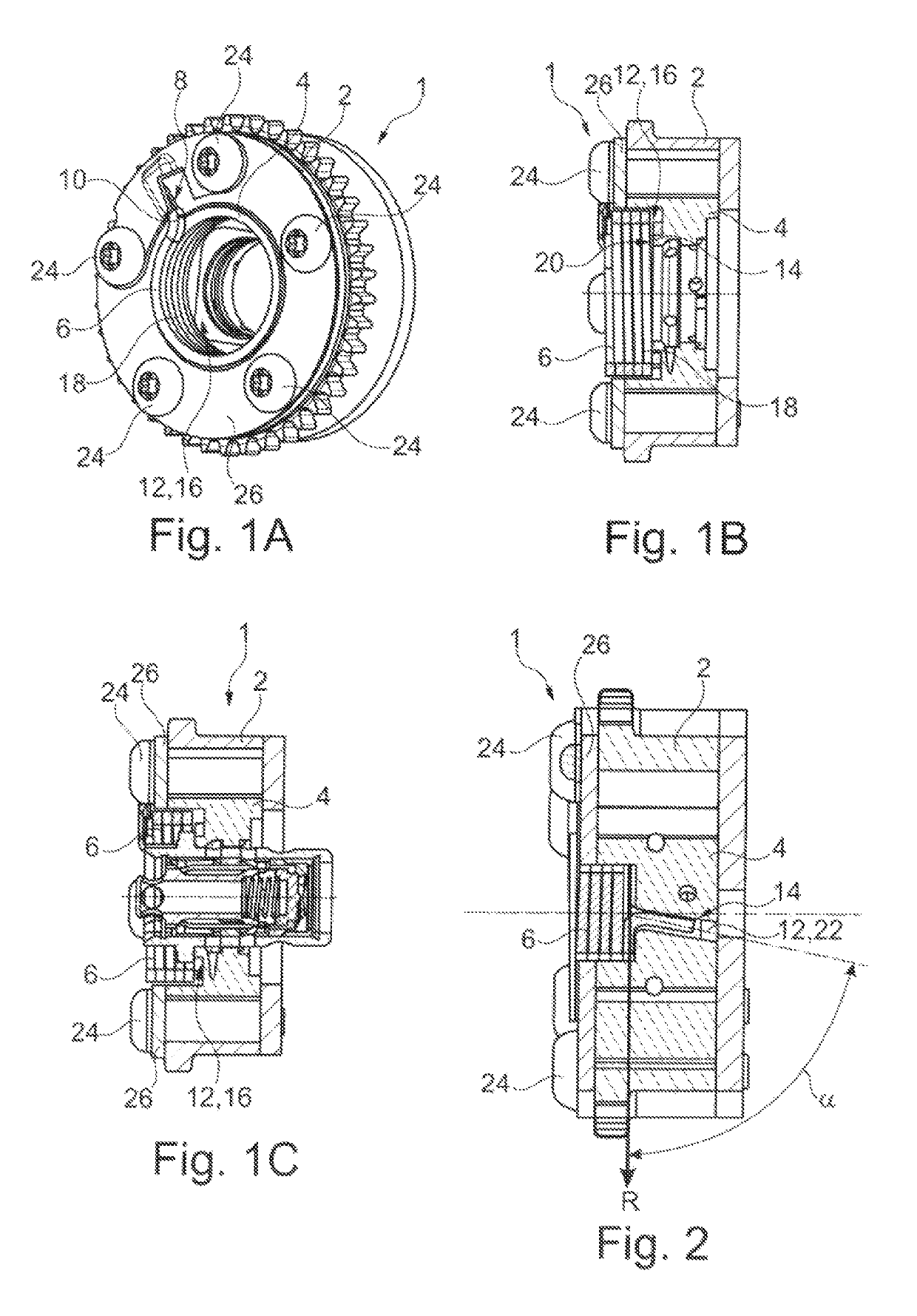
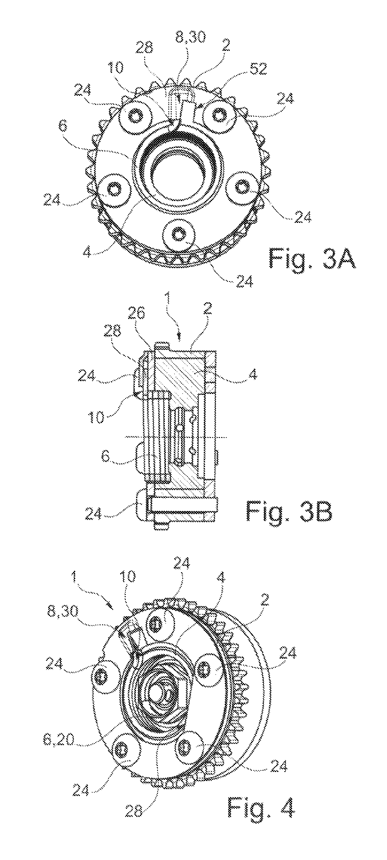
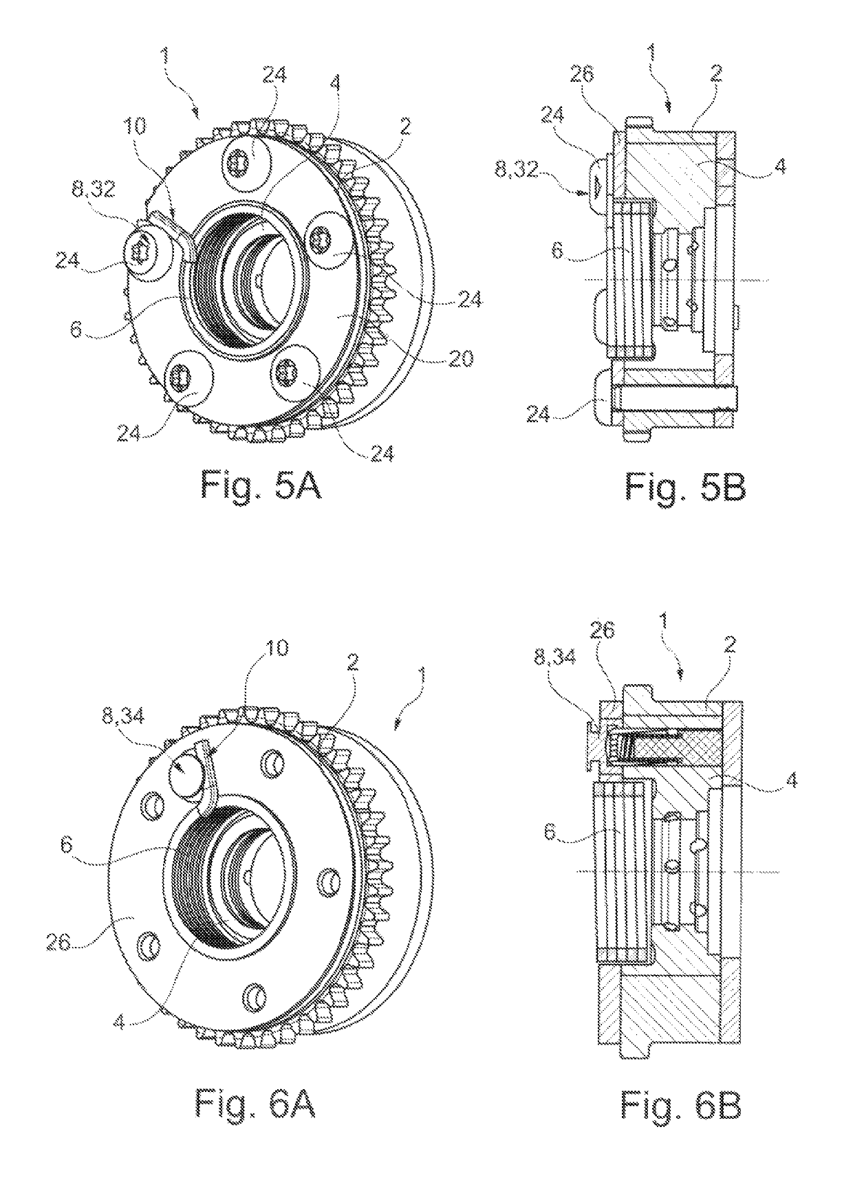
[0036]Identical reference numerals are used for similar or functionally equivalent elements of the present invention. In addition, for the sake of clarity, only reference numerals are illustrated in the individual figures that are necessary for describing the particular figure. The illustrated specific embodiments are used only to illustrate the camshaft adjuster according to the present invention by way of example, but are not to be construed as limiting the present invention.

[0037]FIG. 1A shows a perspective view and FIG. 1B shows a cross-sectional view of a first specific embodiment of camshaft adjuster 1 according to the present invention, which is made up of a stator 2 and a rotor 4. A spring in the form of a coil spring 6 rotatably braces rotor 4 against stator 2, so that a drive torque of a camshaft, not illustrated here, may be compensated for during operation of camshaft adjuster 1. According to the present invention, stator 2 includes a first recess 8 for a first free end ...


PUM


Abstract

A camshaft adjuster (1) including a stator (2) and a rotor (4), a spring (6) tenses the rotor (4) rotationally counter to the stator (2). According to the invention, the spring is a coil spring (6), the stator (2) includes a first recess (8) of a first free end (10) of the coil spring (6) and the rotor (4) includes a second recess (12) for a second free end (14) of the coil spring (6).

Description

[0001]The present invention relates to a camshaft adjuster which includes a stator and a rotor, a spring rotatably bracing the rotor against the stator.BACKGROUND[0002]It is generally known that camshaft adjusters are used in internal combustion engines for varying the timing of the combustion chamber valves. Adjusting the timing to the instantaneous load reduces fuel consumption and emissions. Camshaft adjusters include a stator and a rotor. The rotor is usually connected in a rotatably fixed manner to the camshaft, the rotor being situated within the stator, coaxially with respect to same. The rotor and stator include oil chambers which may be acted on by oil pressure and generate a relative movement between the stator and the rotor.[0003]To allow a torque transmission between the components of rotor and stator and also to compensate for a drive torque of the camshaft, a spring rotatably braces the rotor against the stator. This is described, for example, in German patent specific...

Claims


Application Information

Patent Timeline
Patent Type & Authority Patents(United States)
IPC IPC(8): F01L1/344
CPCF01L1/3442F01L2001/34433F01L2001/34453F01L2001/34483
Inventor SEBALD, STEFANHOELZEL, STEFANPUETZ, BORISBAYRAKDAR, ALI
Owner SCHAEFFLER TECH AG & CO KG
Why Eureka
Try Eureka