Device and method for manipulation and routing of a metrology beam

a metrology beam and device technology, applied in the field of lithographic projection apparatus, can solve the problems of high adjustment resolution, low sensitivity to mechanical changes and/or instabilities, and achieve the effect of improving stability over conventional devices

Active Publication Date: 2007-02-13
ASML NETHERLANDS BV
View PDF16 Cites 0 Cited by
  • Summary
  • Abstract
  • Description
  • Claims
  • Application Information

AI Technical Summary

Benefits of technology

[0020]The principles of the present invention, as embodied and broadly described herein, provide a device

Problems solved by technology

The large ratio between mechanical adjustments made in the manipulating device and their influence on the beam's angular a

Method used


Image

  • Device and method for manipulation and routing of a metrology beam
  • Device and method for manipulation and routing of a metrology beam
  • Device and method for manipulation and routing of a metrology beam

Examples


embodiments

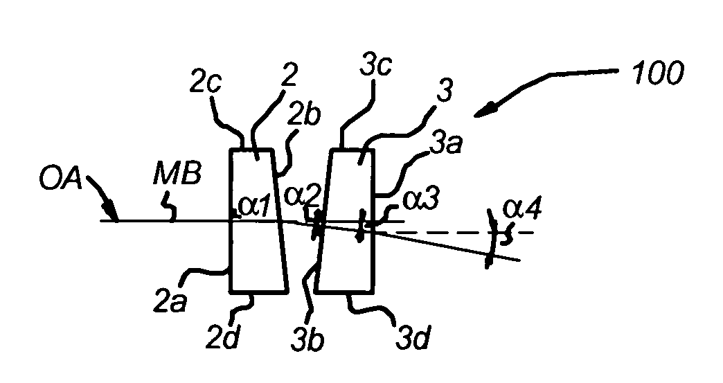
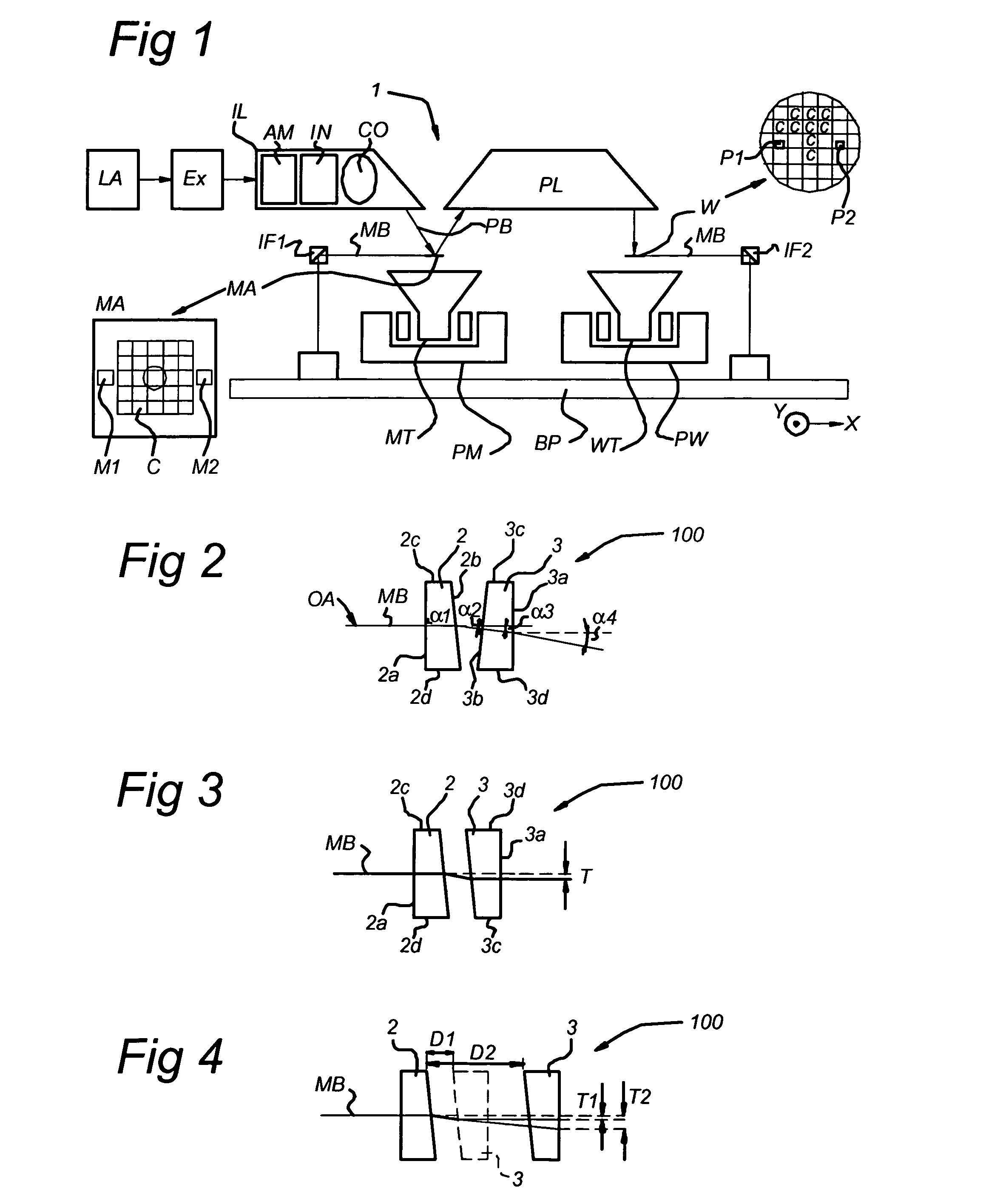
[0053]The interferometric measuring mechanism typically can comprise a light source, such as a laser (not shown), and one or more interferometers for determining some information (e.g., position, alignment, etc.) regarding an object to be measured, such as a substrate or a stage. In FIG. 1, for example, two interferometers IF1 and IF2 are schematically depicted. The light source (laser) produces a metrology beam MB which is routed to the interferometer(s) IF1, IF2 by one or more beam manipulators. In case more than one interferometer is present, the metrology beam is shared between them, by using optics that split the metrology beam in various separate beams for each interferometer. In FIG. 1, for example, shows the metrology beam split into two beams. The splitter optics are not shown. A beam manipulator may also be used in the interferometer itself.

[0054]FIG. 2 schematically shows a cross-section of a device for manipulation and routing of a metrology beam according to an embodime...


PUM


Abstract

A lithographic projection apparatus is equipped with a device for manipulation and routing of at least one portion of a metrology beam of radiation. The device includes a first and a second optical wedge, wherein the second optical wedge and the first optical wedge having a relative position with respect to each other. The at least one portion of the metrology beam enters the device along an incoming optical axis at a first major surface of the first optical wedge, passes through the first and second optical wedges, and exits at a second major surface of the second optical wedge. The first and second optical wedges are arranged to at least one of rotate and translate the at least one portion of the metrology beam relative to the incoming optical axis by changing the relative position of the first and the second optical wedges.

Description

BACKGROUND OF THE INVENTION[0001]1. Priority Information[0002]This application claims priority from European Patent Application No. 03075659.7, filed Mar. 6, 2003, herein incorporated by reference in its entirety.[0003]2. Field of the Invention[0004]The present invention relates to a lithographic projection apparatus, and in particular, to a device for manipulating and routing a metrology beam of radiation and an associated device manufacturing method.[0005]3. Description of the Related Art[0006]Lithographic apparatus can be used, for example, in the manufacture of integrated circuits (ICs). In such a case, a patterning device may be used to generate a desired circuit pattern corresponding to an individual layer of the IC, and this pattern can be imaged onto a target portion (e.g. comprising one or more dies) on a substrate (silicon wafer) that has been coated with a layer of radiation-sensitive material (resist).[0007]The term “patterning device” as here employed should be broadly ...

Claims


Application Information

Patent Timeline
IPC IPC(8): G02B26/08G03F7/20H01L21/027
CPCG03F7/70775G03F7/20
Inventor VAN DER PASCH, ENGELBERTUS ANTONIUS FRANSISCUSBEEMS, MARCEL HENDRIKUS MARIAEUSSEN, EMIEL JOZEF MELANIEKLIJNTUNTE, ENGELBERTUS JOHANNES JEROEN
Owner ASML NETHERLANDS BV
Why Eureka
Try Eureka