
Method for producing a double-layer or triple-layer sound-absorbing panel and corresponding sound-absorbing panel

a sound-absorbing panel and triple-layer technology, applied in the direction of sound-absorbing devices, building components, applications, etc., can solve the problems of reducing the maximum surface area of the sound-absorbing panel, the grooves negatively affecting the smooth connection of the coating to the support panel, so as to achieve a greater sound-absorbing acoustic panel, the production process may be simplified, and the effect of reducing the density of the chip

Inactive Publication Date: 2014-12-30
AKUSTIK & INNOVATION
View PDF19 Cites 0 Cited by
  • Summary
  • Abstract
  • Description
  • Claims
  • Application Information

AI Technical Summary

Benefits of technology

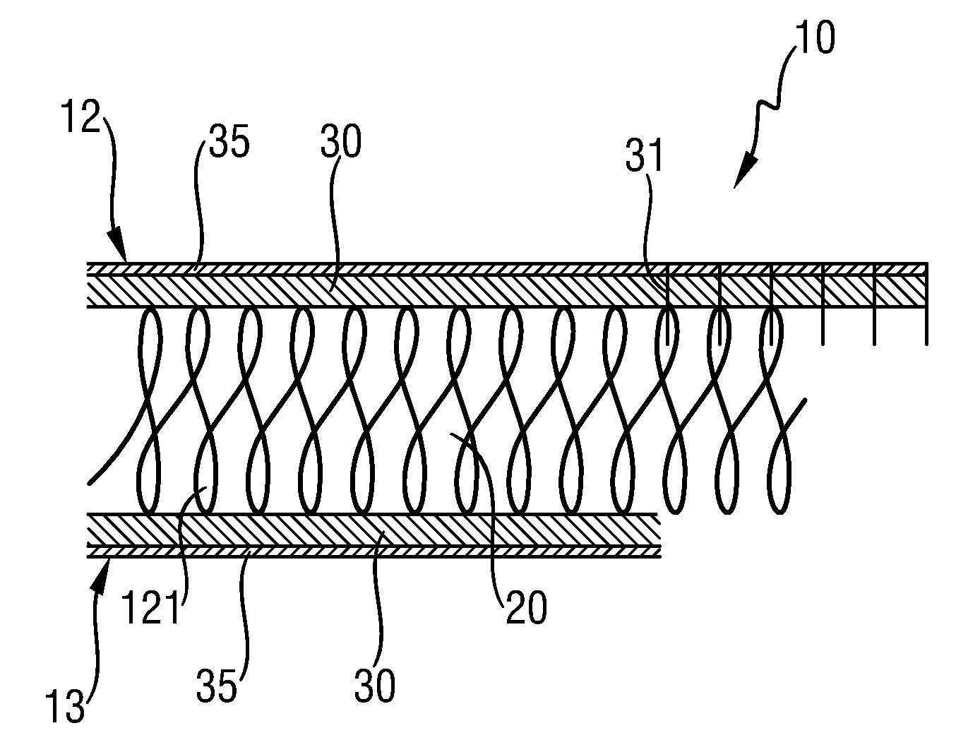
[0008]Proceeding from this prior art, the object of the invention is to specify a method by which a sound-absorbing acoustic panel may be constructed so as to be less costly in terms of treatment. It is, therefore, an object of the invention to produce such a panel in an efficient and cost-effective manner.
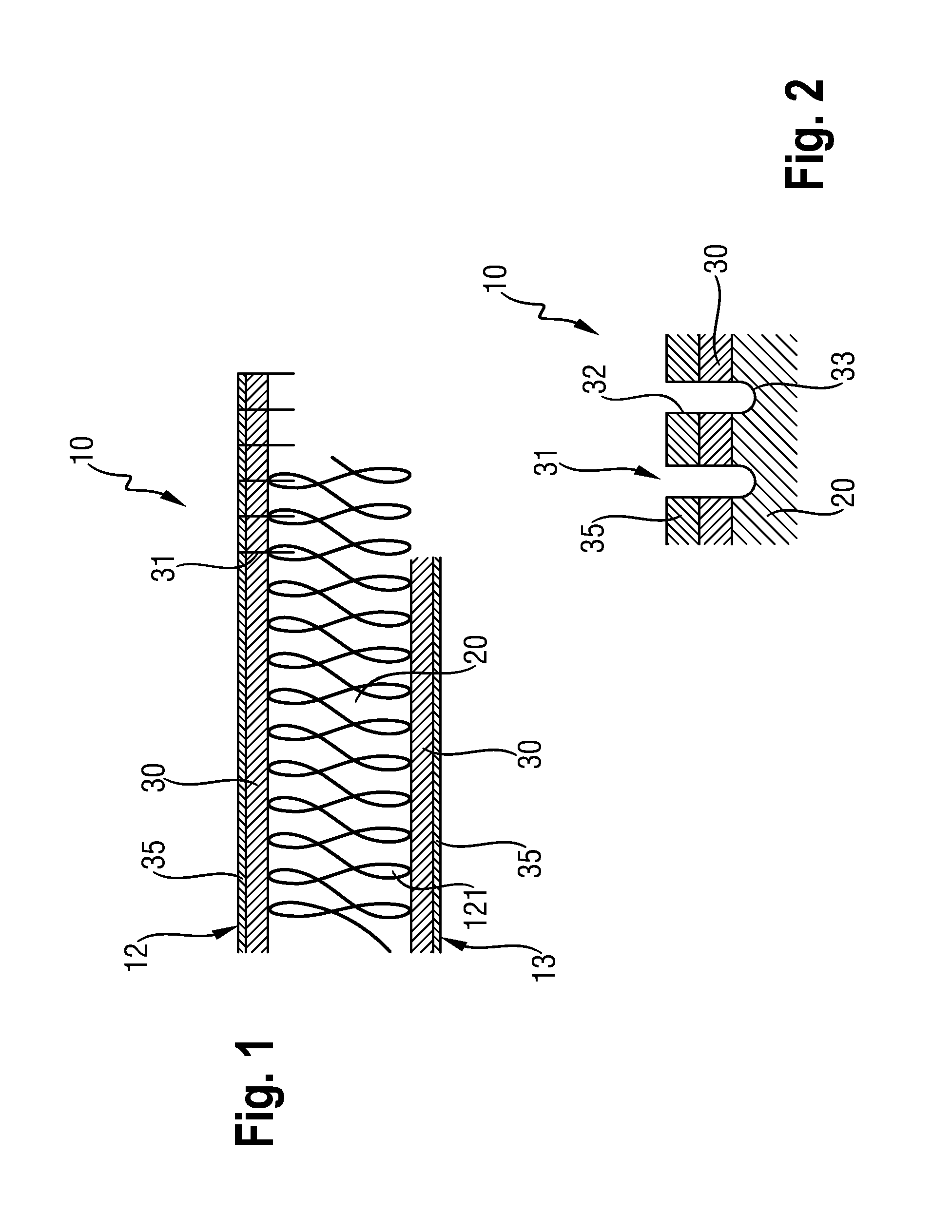
[0011]“Blind hole” is thus understood as a hole which enters the support panel but does not fully penetrate said support panel. By the partial penetration of the blind hole into the support panel, the support panel surface on the blind hole side, which is assigned to a through-hole through the cover panel or top layer, is enlarged. This produces improved sound input from outside into the support panel and thus optimized sound absorption through the panel. In terms of manufacturing technology, it is also advantageous if the continuous hole through the cover panel or top layer and the blind hole in the support panel are able to be introduced in one step by laser perforation and form a single blind hole. Thus, in a single radiation step the through-hole is produced through the cover panel or top layer and the blind hole is produced in the support panel and thus the blind hole in the acoustic panel. Additionally, by the fixed fastening of the cover panel or top layer and support panel before the perforation treatment step, it is ensured that the through-hole and the associated blind hole are optimally always located on top of one another. Thus the sound is then optimally attenuated in the panel. Moreover, the stability of the support panel is weakened less by blind holes than by through-holes. Thus no special measures have to be taken in order to start the drilling process behind the support panel, as the drilling and / or perforation always terminates in the support panel. Additionally, increased error tolerance is present in the depth of the blind hole, as a result of which the introduction of the hole is simpler.
[0018]A panel comprising more pores and internal cavities may be obtained as an open-pore panel by a lighter filling of the chipboard particles being provided during production of the internal panel so that the density of the chipboard particles is reduced. Said chipboard particles are thus compressed to a lesser degree. An essential feature of such an open-pore panel is the efficient provision of a large number of connecting holes preferably on both sides through the laminated materials providing the visual appearance. This is available as a “laminated chipboard panel” with a thin covering material, whilst with thicker top layers it is denoted as “covered chipboard panel”.
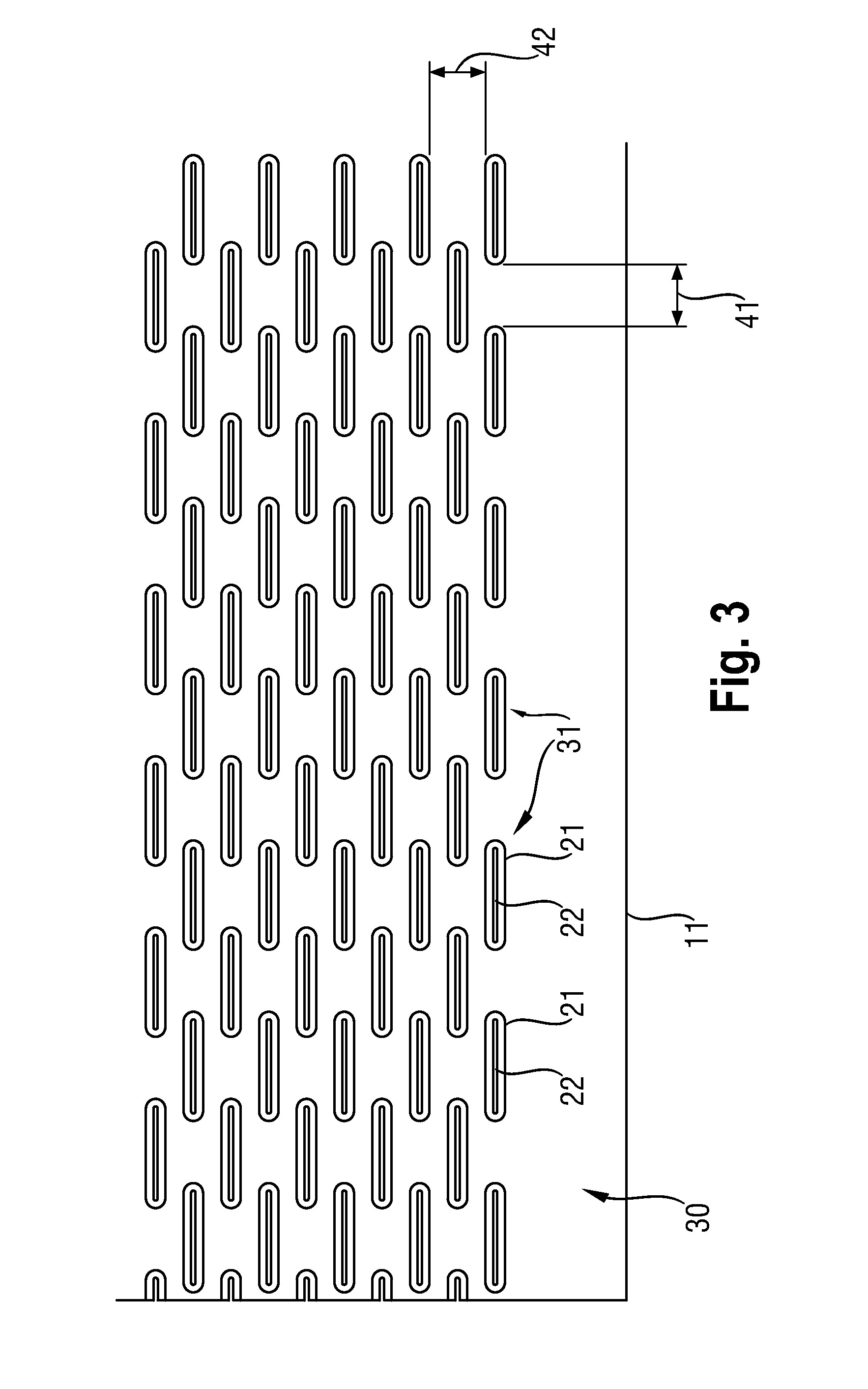
[0019]As previous treatment of the raw chipboard panel is not necessary, this is a great advantage and it permits greater sound-absorbing acoustic panels to be produced. It is surprising that it is sufficient in this case to treat the thin cover panels on both sides with a scanning laser, in order to produce the connection, in terms of sound absorption technology, of the surrounding space with the internal chipboard panel. It is important here that, via the micro-slots produced by the laser, the closed outer layers of the coating or cover panel are perforated and the open central layer of the chipboard panel is cut-into so that a panel which is absorbent in all layers may be produced.

Problems solved by technology

This construction of a sound-absorbing panel is costly, as the central wooden panel is treated over its entire depth; as a result the potential maximum surface area of the sound-absorbing panel is reduced.
Therefore, advantageously in the prior art, grooves are incorporated in the support panel but said grooves negatively influence the smooth connection of the coating to the support panel.

Method used


Image

  • Method for producing a double-layer or triple-layer sound-absorbing panel and corresponding sound-absorbing panel
  • Method for producing a double-layer or triple-layer sound-absorbing panel and corresponding sound-absorbing panel
  • Method for producing a double-layer or triple-layer sound-absorbing panel and corresponding sound-absorbing panel

Examples


Embodiment Construction

[0008]Proceeding from this prior art, the object of the invention is to specify a method by which a sound-absorbing acoustic panel may be constructed so as to be less costly in terms of treatment. It is, therefore, an object of the invention to produce such a panel in an efficient and cost-effective manner.

[0009]This object is achieved according to the invention by a method having the features of Claim 1.

[0010]A method for producing a double-layer or triple-layer sound-absorbing panel is specified, therefore, said panel consisting of a support panel and at least one cover panel or coating of the support panel, the cover panel or coating being fixedly connected to the support panel. In this case, preferably an open-pore support panel is provided as the support panel and the sound-absorbing panel is arranged on each side, provided with a cover panel or coating, with a device opposite said side emitting a laser beam, the upper face of said panel being subjected to the laser beam, which...


PUM

PropertyMeasurementUnit
diameteraaaaaaaaaa
widthaaaaaaaaaa
widthaaaaaaaaaa

Abstract

A method for producing a double-layer or triple-layer sound-absorbing panel (10) is specified, said panel consisting of a support panel (20) and at least one cover panel or coating (30, 35) of the support panel (20), the cover panel or coating (30, 35) being fixedly connected to the support panel (20). In this case, an open-pore (121) support panel is provided as the support panel (20) and the sound-absorbing panel (10) is arranged on each side (12, 13) provided with a cover panel or coating (30, 35) with a device opposing said side emitting a laser beam, the upper face (12) of said panel (10) being subjected to the laser beam, which is designed to burn away material from the cover panel or coating (30, 35) facing said laser beam over the depth in the direction of the laser beam in a plurality of holes (31). In this case, the laser beam acting on the panel (10) is designed such that the waist of the laser beam is focused on a plane parallel to the lower face of the cover panel or top layer (30, 35) such that the holes (31) are continuous through the cover panel or top layer (30, 35), and a lower hole opening / hole end (33) is produced in the support panel (20) itself so that the surroundings are connected to the open-pore support panel (20) via an air connection (121).

Description

TECHNICAL FIELD[0001]The present invention relates to a method for producing a double-layer or triple-layer sound-absorbing panel, in particular a wooden panel having the features of the preamble of Claim 1. The invention further relates to such a double-layer or triple-layer sound-absorbing panel comprising a central panel, in particular made of wood, on which in each case a thin, smooth cover layer is placed on both sides, according to the features of the preamble of Claim 8.PRIOR ART[0002]A triple-layer sound-absorbing wooden panel having the features of the preamble of Claim 8 is disclosed in WO 2006 / 056351. The central support panel consists of a wood-based material into which holes are cut, in particular by drilling. On said support panel at least on one side, advantageously on both sides, cover panels or coatings are applied into which a plurality of holes have been drilled, the holes in the panel and the associated cover panel being at least partially aligned with one anothe...

Claims


Application Information

Patent Timeline
Patent Type & Authority Patents(United States)
IPC IPC(8): E04B1/82G10K11/172E04B1/86G10K11/168B23K26/36B32B3/12E04B1/84
CPCG10K11/168E04B1/84E04B2001/8461G10K11/172E04B1/86B23K26/362E04B2001/849B32B2307/102B32B27/36B32B21/02B32B2479/00B32B27/08Y10T428/24149B32B21/14B32B27/10B32B21/08B23K26/361
Inventor MADER, MARCO
Owner AKUSTIK & INNOVATION
Learn More