Sliding component

a technology of components and components, applied in the direction of engine components, mechanical devices, engine seals, etc., can solve the problems and achieve the effects of preventing the formation of deposits in the fluid circulation groove, ensuring the production of reliable results, and increasing the pressure difference between the inlet portion and the outlet portion of the fluid circulation groov

Active Publication Date: 2019-04-30
EAGLE INDS
View PDF21 Cites 1 Cited by
  • Summary
  • Abstract
  • Description
  • Claims
  • Application Information

AI Technical Summary

Benefits of technology

[0021](1) The fluid circulation groove communicating with the high-pressure fluid side via the inlet portion and the outlet portion and separated from the low-pressure fluid side by the land portion is provided in the sealing face of the one slide part, and the at least one interference groove communicating with the high-pressure fluid side, for producing pressure variations in the fluid in the fluid circulation groove is provided in the sealing face of the other slide part, whereby there is a pressure difference between the inlet portion and the outlet portion of the fluid circulation groove, which is varying alternately, and the fluid in the fluid circulation groove repeats movements. Thus, even when a sealed fluid contains a deposit formation-causing substance, formation of deposits in the fluid circulation groove can be prevented, and the sealing function of the sealing faces can be maintained for a long period of time.
[0022](2) The at least one interference groove includes a plurality of interference grooves that is provided circumferentially and is arranged so that when one of the interference grooves is in a position facing the inlet portion of the fluid circulation groove, the other interference groove or grooves are not in a position facing the outlet portion of the fluid circulation groove. Thus the pressure difference between the inlet portion and the outlet portion of the fluid circulation groove can be increased and produced reliably, and formation of deposits in the fluid circulation groove can be further prevented.
[0023](3) The fluid circulation groove is formed in the stationary-side seal ring, the at least one interference groove is formed in the rotating-side seal ring, the rotating-side seal ring is formed larger in outside diameter and smaller in inside diameter than the stationary-side seal ring, and the at least one interference groove is provided in a position to produce pressure variations in the fluid in the inlet portion and the outlet portion of the fluid circulation groove, whereby the sealing face width depends on the stationary-side seal ring, and thus variation in the sealing face width can be reduced. Further, since the at least one interference groove is formed in the sealing face of the rotating-side seal ring, a swirl flow accompanied by a vortex is actively formed, and the pressure difference between the inlet portion and the outlet portion of the fluid circulation groove can be further increased.
[0024](4) The end of the at least one interference groove on the inside-diameter side extends to a position radially in proximity to the inlet portion and the outlet portion of the fluid circulation groove, whereby the pressure difference between the inlet portion and the outlet portion of the fluid circulation groove can be further increased.
[0025](5) The end of the at least one interference groove on the inside-diameter side extends to a position radially overlapping the inlet portion and the outlet portion of the fluid circulation groove, whereby a pressure-varying effect by the at least one interference groove is exerted directly on the inlet portion and the outlet portion of the fluid circulation groove, and thus the pressure difference between the inlet portion and the outlet portion of the fluid circulation groove can be even further increased.

Problems solved by technology

However, these inventions only introduce a fluid into a sealing face, and do not take measures to prevent formation of deposits on a sealing face.

Method used


Image

  • Sliding component
  • Sliding component
  • Sliding component

Examples


first embodiment

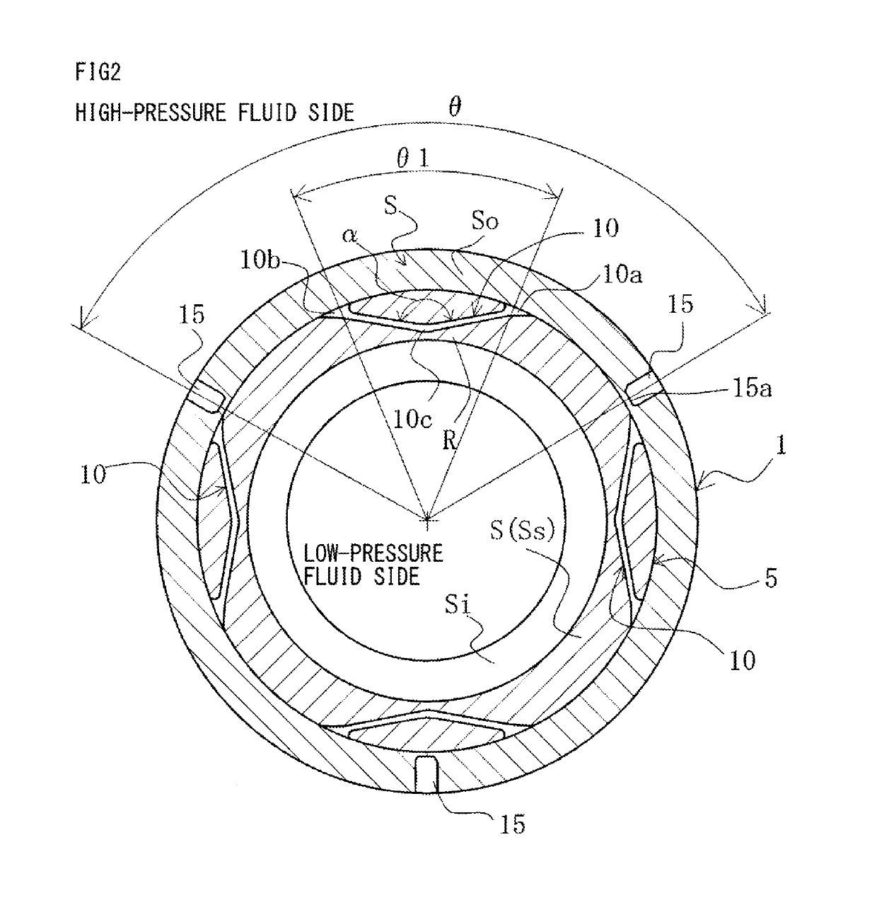
[0033]With reference to FIGS. 1 to 3, a slide component according to a first embodiment of the present invention will be described.

[0034]In the following embodiment, a mechanical seal, an example of the slide component, will be described as an example. The outer-peripheral side of slide parts constituting the mechanical seal is described as the high-pressure fluid side (sealed fluid side), and the inner-peripheral side as the low-pressure fluid side (atmosphere side). However, the present invention is not limited to this, and is applicable to a case where the high-pressure fluid side and the low-pressure fluid side are reversed.

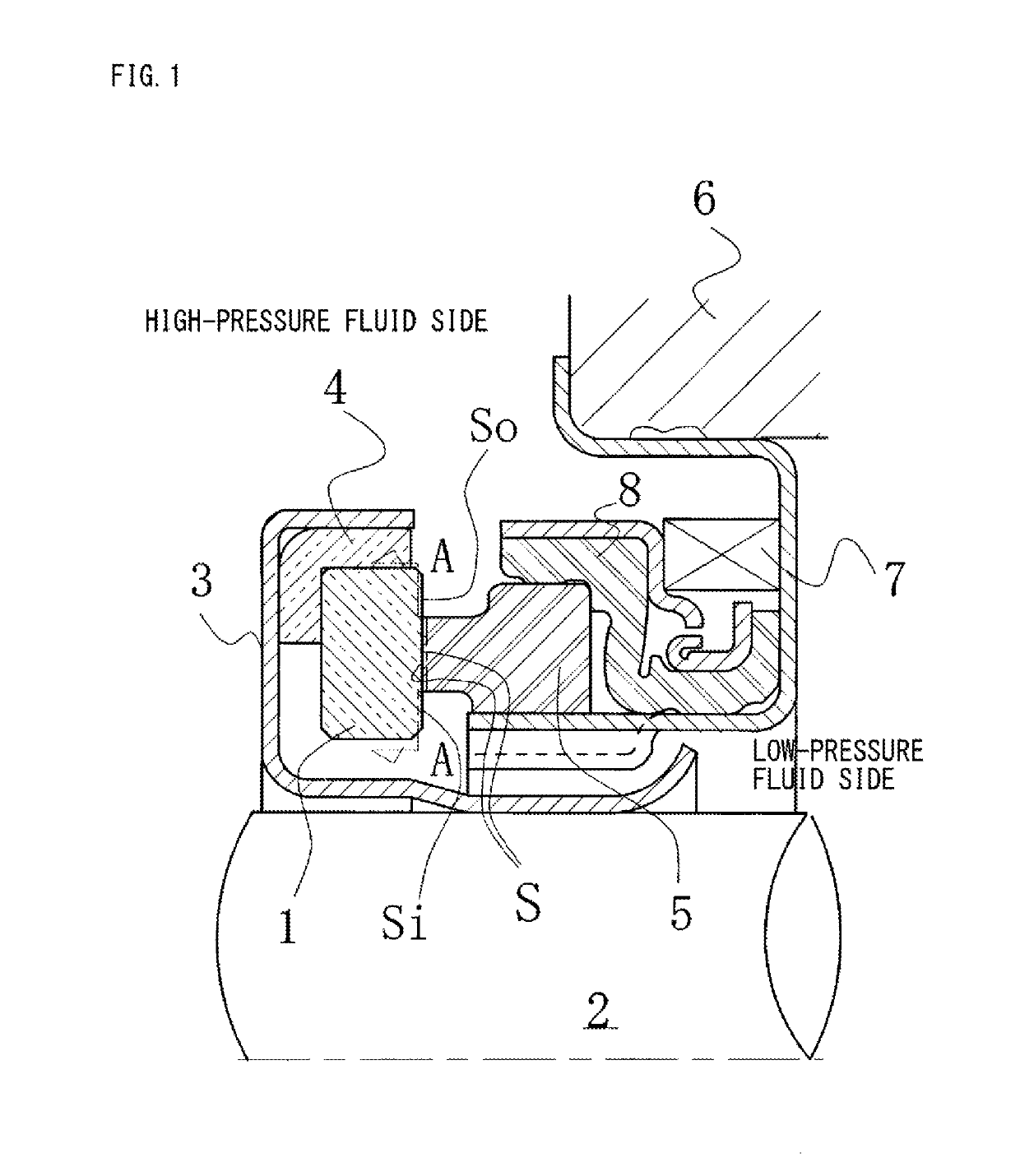
[0035]FIG. 1 is a vertical cross-sectional view showing an example of the mechanical seal, which is an inside mechanical seal in a form of sealing a sealed fluid on the high-pressure fluid side trying to leak from the outer periphery of sealing faces toward the inner periphery. The mechanical seal is provided, on the side of a rotating shaft 2 to drive a roto...

second embodiment

[0065]With reference to FIG. 4, a slide component according to a second embodiment of the present invention will be described.

[0066]The second embodiment is different from the first embodiment in that the number of interference grooves 15 is higher, but is identical with the first embodiment in that the plurality of interference grooves 15 is arranged so that when one of the interference grooves 15 is in a position facing an inlet portion 10a of a fluid circulation groove 10, the other interference grooves 15 are not in a position facing an outlet portion 10b of the fluid circulation groove 10.

[0067]In FIG. 4, the same reference numerals as in FIG. 2 denote the same members, and redundant descriptions will be omitted.

[0068]In FIG. 4, twelve interference grooves 15 are evenly spaced circumferentially. The plurality of interference grooves 15 is arranged so that when one of the interference grooves 15 is in a position facing an inlet portion 10a of a fluid circulation groove 10, the o...

third embodiment

[0071]With reference to FIG. 5, a slide component according to a third embodiment of the present invention will be described.

[0072]The third embodiment is different from the first embodiment shown in FIG. 2 in that ends of interference grooves on the inside-diameter side extend into a sealing portion Ss of a rotating-side seal ring 1, but otherwise identical with the first embodiment.

[0073]In FIG. 5, the same reference numerals as in FIG. 2 denote the same members, and redundant descriptions will be omitted.

[0074]In FIG. 5, a sealing face S of the rotating-side seal ring 1 is provided with three interference grooves 20 evenly spaced circumferentially. The interference grooves 20 communicate with the high-pressure fluid side, and ends 20a of the interference grooves 20 on the inside-diameter side extend to positions radially overlapping inlet portions 10a and outlet portions 10b of fluid circulation grooves 10 as shown by broken lines. That is, the interference grooves 20 are formed ...


PUM


Abstract

Provided is a slide component that can prevent deposit formation on a sealing face as well as promoting circulation of a fluid on sealing faces while fulfilling both conflicting conditions of sealing and lubrication, to maintain the sealing function of the sealing faces for a long period of time. The slide component includes a pair of slide parts that relatively slide on each other, one of the slide parts being provided in a sealing face with fluid circulation grooves 10 that communicate with a high-pressure fluid side via an inlet portion and an outlet portion and are separated from a low-pressure fluid side by a land portion, the other of the slide parts being provided in a sealing face with interference grooves 15 that communicate with the high-pressure fluid side and produce pressure variations in a fluid in the fluid circulation grooves 10.

Description

[0001]This application is the U.S. National Phase under 35 U.S.C. § 371 of International Application PCT / JP2015 / 073945, filed Aug. 26, 2015, which claims priority to Japanese Patent Application No. 2014-192046, filed Sep. 20, 2014. The International Application was published under PCT Article 21(2) in a language other than English.TECHNICAL FIELD[0002]The present invention relates to slide components suitable for, for example, mechanical seals, bearings, and other slide portions, and in particular, relates to slide components such as seal rings or bearings that require friction reduction by interposing a fluid between sealing faces as well as prevention of fluid leakage from the sealing faces.BACKGROUND ART[0003]A mechanical seal, an example of a slide component, is evaluated for its performance by a leakage rate, a wear rate, and torque. In conventional arts, by optimizing the seal material and the sealing face roughness of a mechanical seal, performance is increased, and low leaka...

Claims


Application Information

Patent Timeline
Patent Type & Authority Patents(United States)
IPC IPC(8): F16J15/34F16J15/06
CPCF16J15/3404F16J15/3488F16J15/3412F16J15/062
Inventor ITADANI, MASATOSHISUNAGAWA, KAZUMASATOKUNAGA, YUICHIROINOUE, HIDEYUKIHOSOE, TAKESHIYAMAKAWA, RYOMANEGISHI, YUTAKIRYU, KENJICHIBA, KEIICHIYOSHINO, AKIRAKUBOTA, HIROSHI
Owner EAGLE INDS
Why Eureka
Try Eureka