
Pneumatic joint separator for lower body alignment

a technology of lower body and separator, which is applied in the field of exercise equipment, can solve the problems of affecting the normal movement affecting the function affecting the mobility of the lower body, so as to strengthen the lower body, the spine, and the legs

Active Publication Date: 2019-05-14
GRAHAM RICHARD A
View PDF6 Cites 0 Cited by
  • Summary
  • Abstract
  • Description
  • Claims
  • Application Information

AI Technical Summary

Benefits of technology

The device effectively stretches and aligns spinal vertebrae, enhances fluid transport, and strengthens lower body muscles, thereby improving spinal health and mobility by urging the spine into a natural elliptical alignment and lubricating joints.

Problems solved by technology

Without the seepage of fluids into the spinal column, the discs will further dehydrate, which may result in further loss of mobility, crippling, and even nerve damage.
In individuals with lost or reversed cervical and lumbar spinal curves due to injury, illness, genetic predisposition, habitual microtrauma or simply poor posture, the weight of the body bears forwardly on the soft, non-bony intervertebral discs, inhibiting fluid transfer and causing the discs to wear, dehydrate and degenerate.
Over time, these individuals exhibit a significant loss of natural joint movement.
Without this seepage of fluids into the spinal column, the discs will further dehydrate, which may result in further loss of mobility, crippling and possible nerve damage.

Method used


Image

  • Pneumatic joint separator for lower body alignment
  • Pneumatic joint separator for lower body alignment
  • Pneumatic joint separator for lower body alignment

Examples


Embodiment Construction

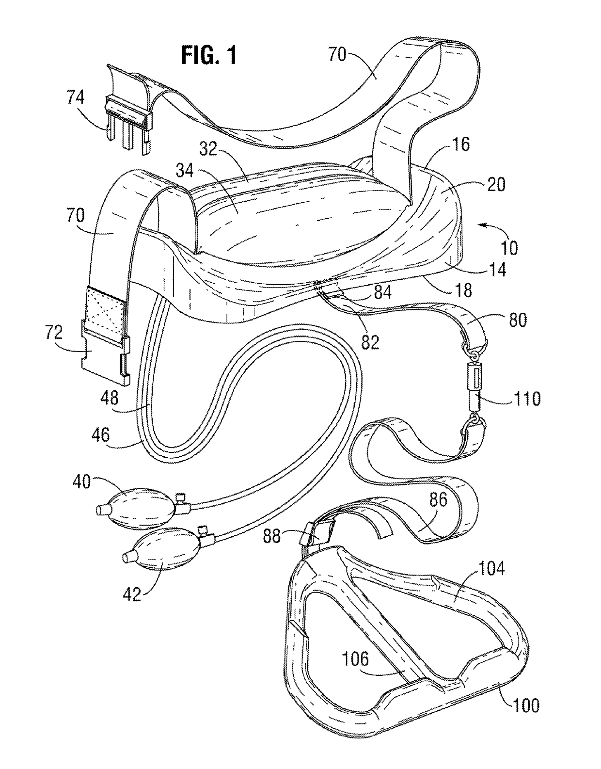
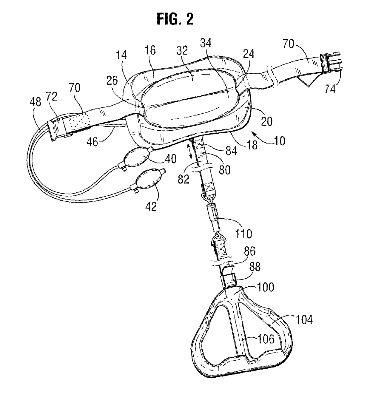
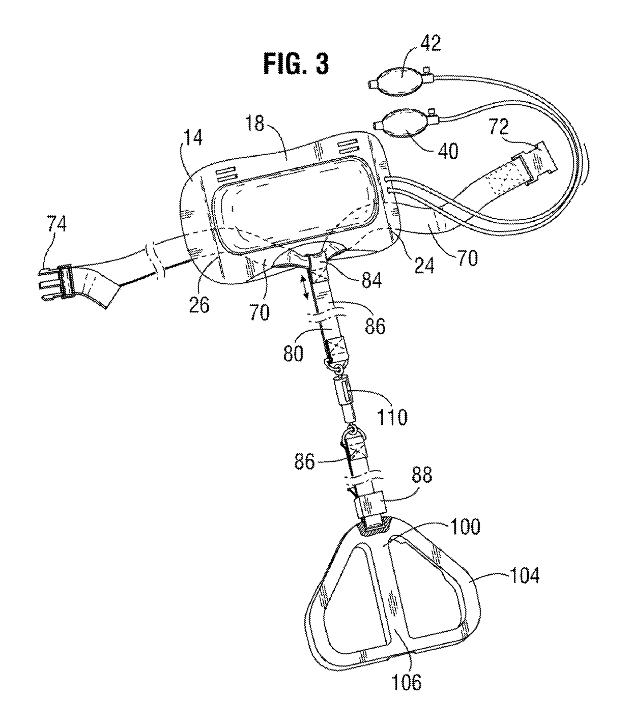
[0041]With reference to FIGS. 1-4 there is shown a leg muscle, abdominal muscle, and spinal exercise device 10 which includes a frame 14 having a top surface 16 and a bottom surface 18. As best seen in FIGS. 1 and 4, the top surface 16 includes a concave surface 20 and, as best seen in FIG. 3 a bottom surface 18.

[0042]The frame 14 structure is preferably molded in suitable lightweight plastic for enabling interconnection of the two inflatable bladders 32, 34 to the top surface 16. As best seen in FIG. 4, the concave surface 20 of the frame 14 includes a hollow portion 22 and slotted 24, 26 portions for enabling interconnection the air bladders 32, 34 and interconnection of the body strap attachment 70.

[0043]With reference to FIG. 2, the inflatable bladders 32, 34 carried by the frame 14 are defined by an upper 32 and a lower portion 34 which are disposed proximate a center of the frame top surface 16. With reference to FIGS. 2 and 4, the air bladders 32, 34 are pneumatically inflate...


PUM


Abstract

A leg muscle, abdominal muscle, and spinal exercise device adapted for imparting curvature to a lumbar or sacral spine of a user and for manipulating the spine and intervertebral discs with decompression force includes a frame for placement on a floor. The frame has a top surface and a bottom surface, wherein the top surface and bottom surface are in a spaced apart relationship forming a hollow portion there between. At least one inflatable bladder is carried by the top surface of the frame. A body strap attachment passes through the frame in non-fixed relationship and is partially disposed within the hollow portion for encompassing the user's thoracic-sacral spinal region and securing said frame. An elongate stirrup strap member is attachable to the body strap attachment thereby connecting to the user's spinal region. A stirrup is attachable to the stirrup strap member distal end.

Description

CROSS-REFERENCE TO RELATED APPLICATIONS[0001]This application is a continuation-in-part application to application Ser. No. 12 / 970,539 filed on Dec. 16, 2010 the entire contents of which are fully incorporated herein with this reference.FIELD OF THE INVENTION[0002]The present invention relates to an exercising device directed at alignment of the lower body and spinal vertebrae. More specifically, the present invention relates to the apparatus and methods for decompressing the spinal vertebrae using the pulling forces of the lower body, leg muscles, and abdominal muscles to urge and correct aberrant spinal vertebrae postures.BACKGROUND OF THE INVENTION[0003]The spinal column is a bony column forming the main structural support of the skeleton of a human being and it consists of bony vertebrae linked by flexible joints and held together by ligaments and flexible gelatinous discs of cartilage. The spinal column of an adult human being consists of thirty-three vertebrae in which the las...

Claims


Application Information

Patent Timeline
Patent Type & Authority Patents(United States)
IPC IPC(8): A61F5/00A63B21/00A61H1/00A61F5/01A63B21/04A63B23/04A63B23/02
CPCA61H1/006A63B21/0004A63B21/00043A63B21/0428A63B21/15A63B21/151A63B21/4009A63B21/4025A63B21/4034A63B23/0205A63B23/0216A63B23/0233A63B23/0238A63B23/0494A61F5/01A63B2225/62A63B2213/00A63B2225/01
Inventor GRAHAM, RICHARD A.
Owner GRAHAM RICHARD A
Learn More