System fault diagnosis via efficient temporal and dynamic historical fingerprint retrieval

a dynamic historical fingerprint and fault diagnosis technology, applied in the field of fault diagnosis, can solve the problems of difficult, if not impossible, to obtain a precise system architecture beforehand, and is usually difficult to obtain such relationships precisely, so as to achieve the effect of mitigating expected harm

Active Publication Date: 2019-05-14
NEC CORP
View PDF8 Cites 1 Cited by
  • Summary
  • Abstract
  • Description
  • Claims
  • Application Information

AI Technical Summary

Benefits of technology

[0004]According to an aspect of the present principles, a computer-implemented method is provided for single modal fault diagnosis. The method includes constructing, by a processor using an invariant model, a fault fingerprint based on a fault event. The method also includes deriving, by the processor using dynamic time warping and at least one convolution, a similarity matrix between the fault fingerprint and one or more historical representative fingerprints. The method additionally includes determining, by the processor, a corrective action correlated to the fault fingerprint, from among a plurality of candidate corrective actions associated with the one or more historical representative fingerprints, based on a unity similarity obtained by processing the similarity matrix. The method also includes initiating, by the processor, the corrective action on a hardware device to mitigate expected harm to at least one item selected from the group consisting of the hardware device, another hardware device related to the hardware device, and a person related to the hardware device.

Problems solved by technology

With the increasing of system complexity, it is hard, if not impossible, to obtain a precise system architecture beforehand.
In real applications, however, it is usually hard to obtain such relationships precisely.
These approaches generally focus on locating the faulty components, they are not capable of spotting or ranking the causal anomalies, thus they are not able to give action suggestions.

Method used


Image

  • System fault diagnosis via efficient temporal and dynamic historical fingerprint retrieval
  • System fault diagnosis via efficient temporal and dynamic historical fingerprint retrieval
  • System fault diagnosis via efficient temporal and dynamic historical fingerprint retrieval

Examples


Embodiment Construction

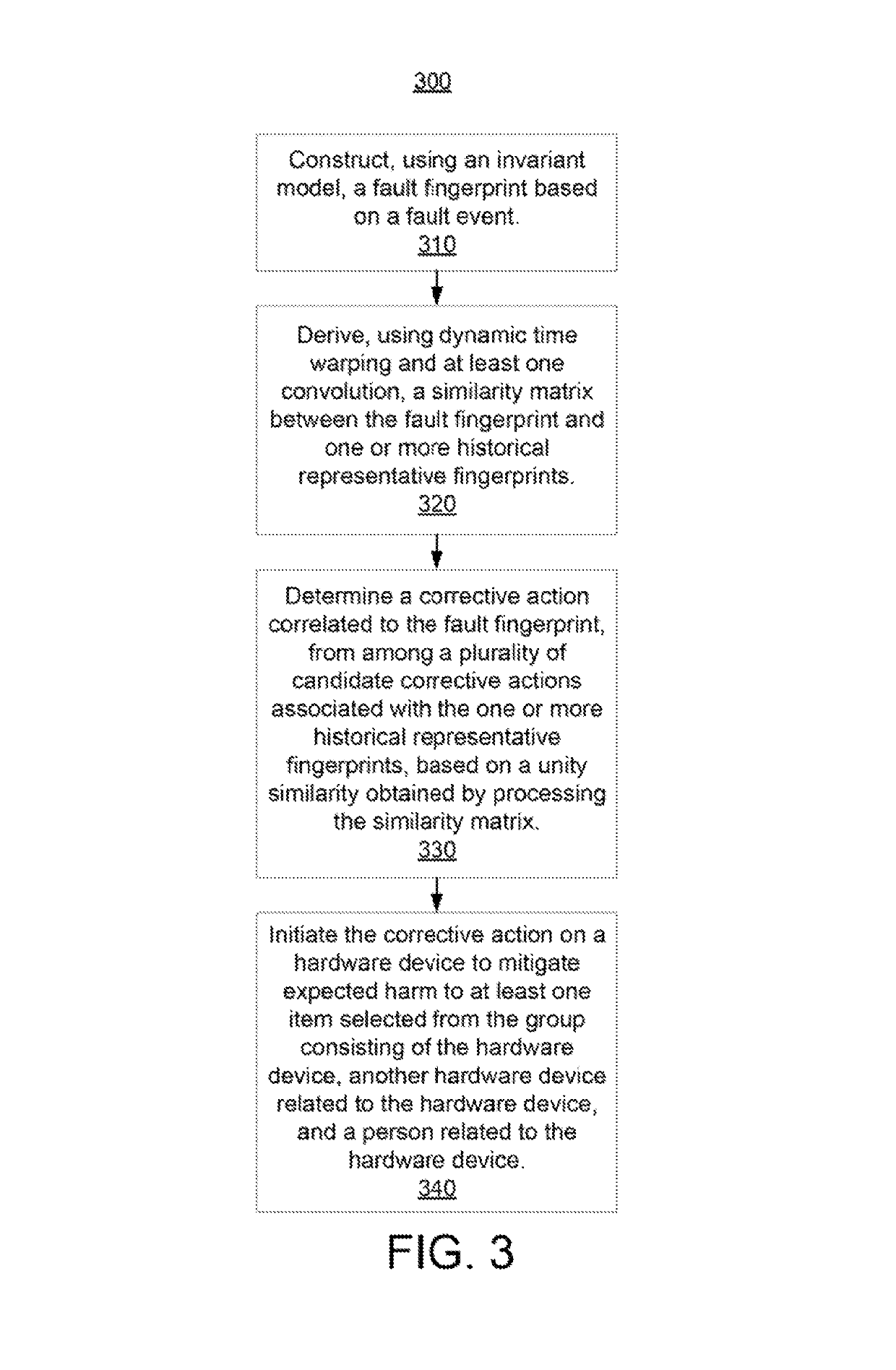
[0014]Since many system faults also occur repeatedly, it is possible to diagnose system failure by retrieval from a historical symptom database. Specifically, an embodiment may extract the system fingerprint based on an invariant model, which learns the dependencies between system components. When a failure happens, a sequence of broken invariants is recorded in a binary matrix to represent the temporal and dynamic failure behavior. A fingerprint database is built to store all such historical system fault fingerprints as well as their failure reasons or possible action annotations. Then the system fault diagnosis solves the problem of symptom fingerprint retrieval, which highly depends on the similarity measurement between a query fingerprint temporal matrix and the historical fingerprint records. The case of single modal symptom retrieval and the multimodal symptom retrieval are decoupled. For a multimodal symptom, the fingerprint matrix is compacted into a feature vector, then a c...


PUM


Abstract

Methods are provided for both single modal and multimodal fault diagnosis. In a method, a fault fingerprint is constructed based on a fault event using an invariant model. A similarity matrix between the fault fingerprint and one or more historical representative fingerprints are derived using dynamic time warping and at least one convolution. A feature vector in a feature subspace for the fault fingerprint is generated. The feature vector includes at least one status of at least one system component during the fault event. A corrective action correlated to the fault fingerprint is determined. The corrective action is initiated on a hardware device to mitigate expected harm to at least one item selected from the group consisting of the hardware device, another hardware device related to the hardware device, and a person related to the hardware device.

Description

RELATED APPLICATION INFORMATION[0001]This application claims priority to U.S. Provisional Patent Application Ser. No. 62 / 327,489 filed on Apr. 26, 2016, incorporated herein by reference in its entirety.BACKGROUNDTechnical Field[0002]The present invention generally relates to fault diagnosis and more particularly to system fault diagnosis via efficient temporal and dynamic historical fingerprint retrieval.Description of the Related Art[0003]A central task in running large scale distributed systems and cyber-physical systems is to automatically monitor the system status and diagnose system fault, so as to guarantee stable and high-quality services or outputs. Significant research efforts have been devoted to this topic. Traditional approaches rely on thorough understandings of the system architecture to build system models and the predefined rules for the diagnosis. With the increasing of system complexity, it is hard, if not impossible, to obtain a precise system architecture beforeh...

Claims


Application Information

Patent Timeline
Patent Type & Authority Patents(United States)
IPC IPC(8): G06F11/00H04L12/24G06F11/07
CPCG06F11/0793H04L41/064G06F11/0709G06F11/079
Inventor CHENG, WEIYOSHIHIRA, KENJICHEN, HAIFENGJIANG, GUOFEI
Owner NEC CORP
Why Eureka
Try Eureka