Head-mounted display device, computer program, and control method for head-mounted display device

a display device and display device technology, applied in the field of head-mounted display devices, can solve the problems of difficult operation of the operation section of the head-mounted display device, deteriorating the visibility of the outside scene depending on the displayed image, etc., to improve the convenience of users and improve the accuracy of inputs.

Active Publication Date: 2019-05-21
SEIKO EPSON CORP
View PDF5 Cites 2 Cited by
  • Summary
  • Abstract
  • Description
  • Claims
  • Application Information

AI Technical Summary

Benefits of technology

[0005]An advantage of some aspects of the invention is to improve accuracy of an input by a pointer and improve convenience for a user.

Problems solved by technology

In a head-mounted display device that is mounted on the head of a user and causes the user to visually recognize an image over an outside scene, visibility of the outside scene is deteriorated depending on a displayed image.
Therefore, it is sometimes difficult to operate an operation section of the head-mounted display device.

Method used


Image

  • Head-mounted display device, computer program, and control method for head-mounted display device
  • Head-mounted display device, computer program, and control method for head-mounted display device
  • Head-mounted display device, computer program, and control method for head-mounted display device

Examples


first embodiment

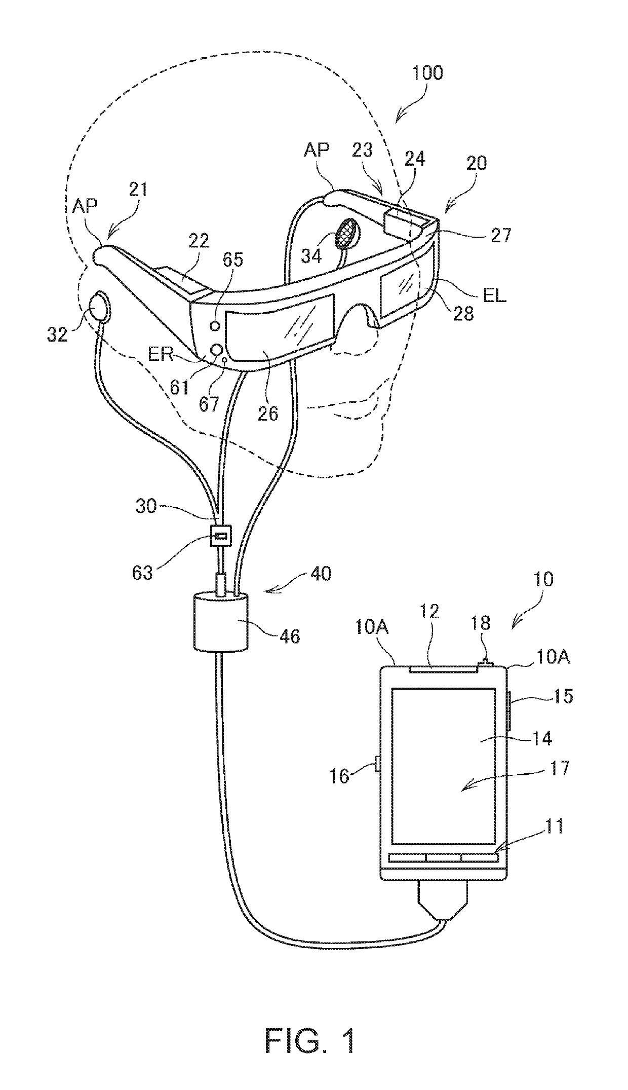
[0072]FIG. 1 is an exterior view showing an exterior configuration of an HMD (Head Mounted Display: head-mounted display device) 100 applied with the invention.

[0073]The HMD 100 is a display device including an image display section 20 (a display section) that is worn on the head of a user and causes the user to visually recognize a virtual image and a control device 10 that controls the image display section 20. A person wearing the image display section 20 on the head is referred to as user.

[0074]The control device 10 includes a flat box-shaped case 10A (also considered to be a housing or a main body) as shown in FIG. 1. The case 10A includes a button 11, an LED indicator 12, a track pad 14, an up / down key 15, a changeover switch 16, and a power switch 18. The button 11, the track pad 14, the up / down key 15, the changeover switch 16, and the power switch 18 are operation sections operated by the user. The LED indicator 12 functions as, for example, a sub-display section that displ...

second embodiment

[0316]FIG. 16 is a diagram showing a state of use of the HMD 100 in a second embodiment.

[0317]FIG. 16 shows a scene in which a plurality of users wearing HMDs 100 make conversation using text data. In particular, FIG. 16 shows a scene in which a user A and a user B make conversation. In the following explanation, the HMD 100 worn by the user A is referred to as “HMD 100A” and the HMD 100 worn by the user B is referred to as “HMD 100B”. In the following explanation, a sign “A” is added to functional sections (see FIG. 4) configuring the HMD 100A and a sign “B” is added to functional sections (see FIG. 4) configuring the HMD 100B.

[0318]The user A and the user B make conversation in a state in which the user A and the user B face each other.

[0319]In the state in which the user A and the user B face each other, a camera 61A of the HMD 100A images a gesture and a hand sign performed by the user B besides a gesture and a hand sign performed by the user A. Similarly, a camera 61B of the HM...

third embodiment

[0340]In a third embodiment, as in the second embodiment, a scene is assumed in which the HMDs 100 are worn on a plurality of users and the users make conversation using texts. In this embodiment, a gesture or a hand sign performed by the user A is detected by the HMD 100A and a gesture or a hand sign performed by the user B is detected by the HMD 100B.

[0341]The control section 150A of the HMD 100A images a gesture or a hand sign performed by the user A with the camera 61A and specifies a text corresponding to the gesture or the hand sign input from picked-up image data. Similarly, the control section 150B of the HMD 100B images a gesture or a hand sign performed by the user B with the camera 61B and specifies a text corresponding to the gesture or the hand sign input from picked-up image data. In this embodiment, the user A and the user B do not need to face each other.

[0342]A communication section 117A of the HMD 100A worn by the user A and a communication section 117B of the HMD ...


PUM


Abstract

An HMD includes an image display section configured to display an image in a display region to be transmitted through an outside scene and recognizable together with the outside scene, a camera and an imaging control section configured to detect a pointer associated with a motion of the user in a region including at least a range in which the image is transmitted through the image display section, and a display control section configured to cause the image display section to display, in the display region, an image indicating a detection state of the pointer by the camera and the imaging control section and cause the display section to display a candidate of input content corresponding to at least any one of a movement, a shape, and a position of the pointer detected by the camera and the imaging control section.

Description

BACKGROUND1. Technical Field[0001]The present invention relates to a head-mounted display device, a computer program, and a control method for the head-mounted display device.2. Related Art[0002]There has been known a device that detects a movement or the like of a pointer and executes processing corresponding to the detected movement or the like of the pointer (see, for example, JP-A-2012-252581 (Patent Literature 1).[0003]Patent Literature 1 discloses a sign language recognition device that images a finger character of a sign language signer, processes picked-up image data picked up by the imaging, and recognizes the finger character of the sign language signer.[0004]In a head-mounted display device that is mounted on the head of a user and causes the user to visually recognize an image over an outside scene, visibility of the outside scene is deteriorated depending on a displayed image. Therefore, it is sometimes difficult to operate an operation section of the head-mounted displ...

Claims


Application Information

Patent Timeline
Patent Type & Authority Patents(United States)
IPC IPC(8): G06F3/0346G06F3/01G06F3/042G06F3/038
CPCG06F3/0346G06F3/017G06F3/0425G06F3/038G06F2203/0384G06F3/012G06F3/04847
Inventor FUJIMAKI, YUTAKATAKANO, MASAHIDE
Owner SEIKO EPSON CORP
Why Eureka
Try Eureka