
Flexible bottom shell and flexible display device

a flexible display and bottom shell technology, applied in the field of displays, can solve the problems of poor display and poor display, and achieve the effect of poor display

Active Publication Date: 2019-05-28
WUHAN CHINA STAR OPTOELECTRONICS TECH CO LTD
View PDF10 Cites 19 Cited by
  • Summary
  • Abstract
  • Description
  • Claims
  • Application Information

AI Technical Summary

Benefits of technology

[0005]The aim of the present disclosure is to provide a flexible bottom shell comprising a plurality of connection plates hinging with each other, when the flexible bottom shell bends, the connection plates have a uniform stress at the bendable position of the flexible display panel, further avoiding folds appearing in the flexible display device which affect display, and solving the issue that when the flexible display devices of the prior art bend, serious folds appear in the bendable position of the flexible display devices, further causing poor display.
[0054]Beneficial effects of the present disclosure are: compared with the flexible display device of prior art, the present disclosure provides the flexible bottom shell of the flexible display device, when the flexible bottom shell bends, the connection plates have a uniform stress at the bendable position of the flexible display panel, further avoiding folds appearing in the flexible display device which affect display, and solving the issue that when the flexible display devices of the prior art bend, more serious folds appear in the bendable position of the flexible display devices, further causing poor display.

Problems solved by technology

However, when the flexible display devices of the prior art bends, serious folds appear in a bendable part of the flexible display devices, further causing poor display.
In summary, if the flexible display devices of the prior art do not have a good bendable structure for support, when the flexible display devices of the prior art bend, serious folds appear in the bendable part of the flexible display devices, further causing poor display.

Method used


Image

  • Flexible bottom shell and flexible display device
  • Flexible bottom shell and flexible display device
  • Flexible bottom shell and flexible display device

Examples


Embodiment Construction

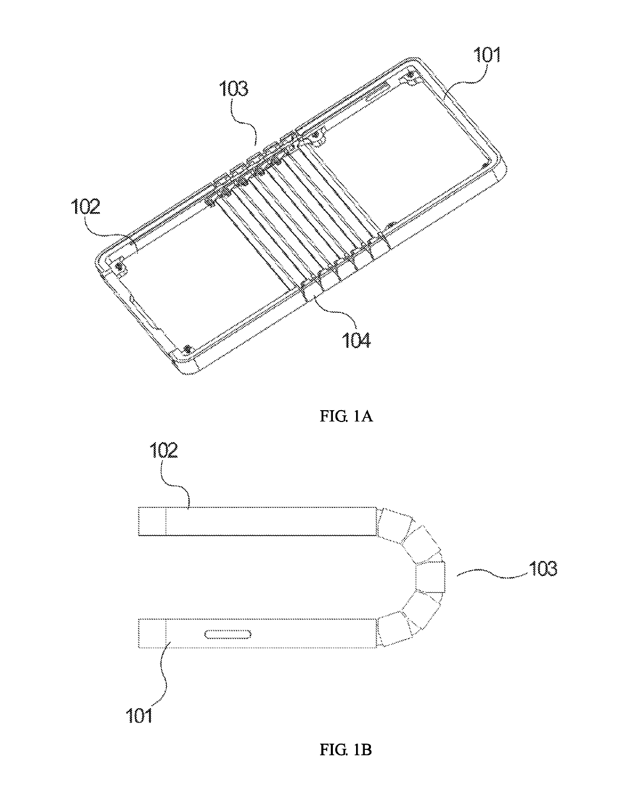
[0061]The following description of every embodiment with reference to the accompanying drawings is used to exemplify specific embodiments which may be carried out in the present disclosure. Directional terms mentioned in the present disclosure, such as “top”, “bottom”, “front”, “back”, “left”, “right”, “inside”, “outside”, “side”, etc., are only used with reference to the orientation of the accompanying drawings. Therefore, the used directional terms are intended to illustrate, but not to limit, the present disclosure. In the drawings, components having similar structures are denoted by same numerals.

[0062]The present disclosure can solve the technical issue that when a flexible display device of the prior art bends, more serious folds appear in a bendable position of the flexible display device, further causing poor display.

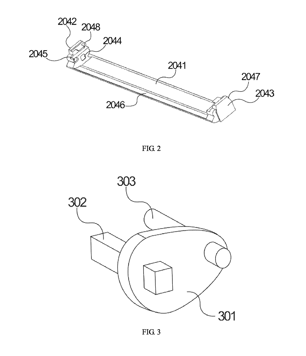
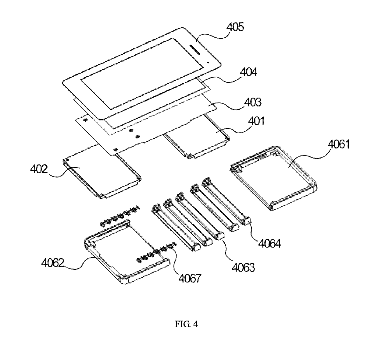
[0063]As shown in FIG. 1A, a flexible bottom shell of the present disclosure is disposed on a display device, where the flexible bottom shell comprises a first ...


PUM

PropertyMeasurementUnit
flexibleaaaaaaaaaa
structuresaaaaaaaaaa
rotation angleaaaaaaaaaa

Abstract

The present disclosure provides a flexible bottom shell, where the flexible bottom shell includes a first half shell, a second half shell, and a bendable part connected the first half shell and the second half shell, where the bendable part includes a plurality of connection plates, the plurality of the connection plates are successively bonded and are successively hinged together. Hinge pieces include a fixed plate, a fixed axle, and a pin axle. The fixed axle and the pin axle are perpendicular to a surface of the fixed plate. The fixed axle is connected to the fixed plate, and the pin axle is connected to the adjacent connection plates.

Description

BACKGROUND OF THE INVENTION1. Field of the Invention[0001]The present disclosure relates to the field of displays, and more particularly to a flexible bottom shell and a flexible display device.2. Description of the Prior Art[0002]Organic light emitting diodes (OLED) display devices are a new type of flat panel display devices. OLED display devices have more advantages, such as easy manufacturing process, low cost, low power dissipation, high lamination brightness, great working temperature range, a thin profile, fast response speed, and easily acts as a flexible display. Therefore, OLED display devices have vast application prospects.[0003]Some flexible display devices in the prior art can bend in the shape of an arc, to make the screen of the display device freely switch between a flat status and a small curvature surface status. However, when the flexible display devices of the prior art bends, serious folds appear in a bendable part of the flexible display devices, further causi...

Claims


Application Information

Patent Timeline
Patent Type & Authority Patents(United States)
IPC IPC(8): H05K5/00H05K5/02E05D7/00E05D3/06H04M1/02G02F1/13H01L51/52
CPCH05K5/0226E05D3/06E05D7/00G02F1/13H04M1/0202H05K5/0017H01L2251/5338E05Y2800/205E05Y2800/244E05Y2900/606H01L51/5237H04M1/0214G06F1/1652G06F1/1656G06F1/1681H10K50/84H10K2102/311
Inventor BI, WEIHSU, CHIH MINGWANG, JUANJUAN
Owner WUHAN CHINA STAR OPTOELECTRONICS TECH CO LTD
Learn More