
Display panel

a display panel and panel technology, applied in the field of electronic devices, can solve the problems of discontinuous flaring, poor display, unsatisfactory display, etc., and achieve the effect of reducing the moiré effect and small thickness

Active Publication Date: 2020-05-05
AU OPTRONICS CORP
View PDF20 Cites 1 Cited by
  • Summary
  • Abstract
  • Description
  • Claims
  • Application Information

AI Technical Summary

Benefits of technology

The design reduces the thickness of the display panel, alleviates Moiré effects, and eliminates dimming offsets, resulting in improved display quality by eliminating the need for two independent panels and simplifying the structure.

Problems solved by technology

However, stacking two display panels often produces an issue in alignment accuracy, and interference fringes are generated due to Moiré effect as a result, such that the display is unsatisfactory.
Moreover, since the structure formed by stacking two display panels is thicker, the light from the shutter panel may be incident at an angle to a region in the display panel not to be irradiated, such that dimming offset occurs at a non-normal angle of view, thus causing the issues of poor display (such as ghost image and / or discontinuous flaring).

Method used


Image

  • Display panel
  • Display panel
  • Display panel

Examples


Embodiment Construction

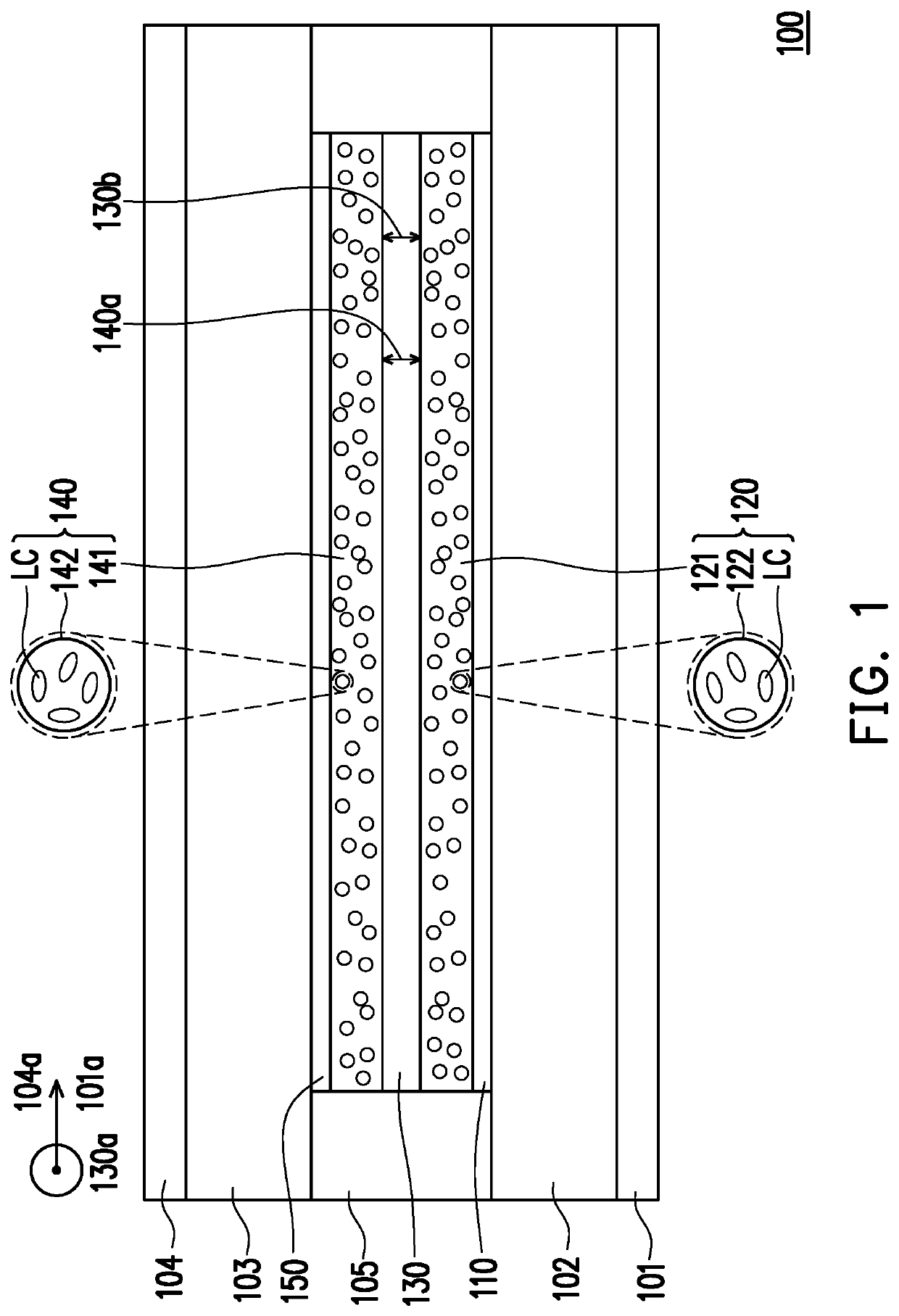
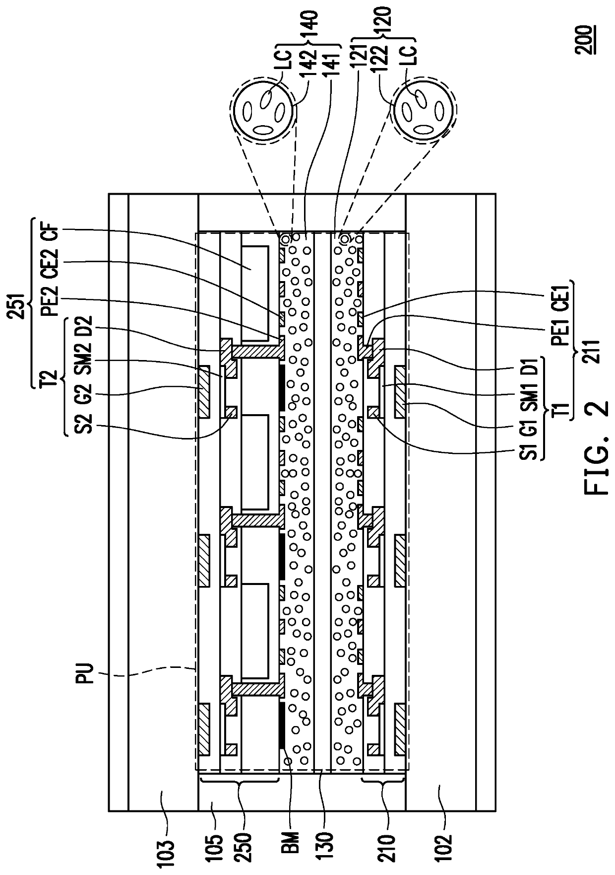
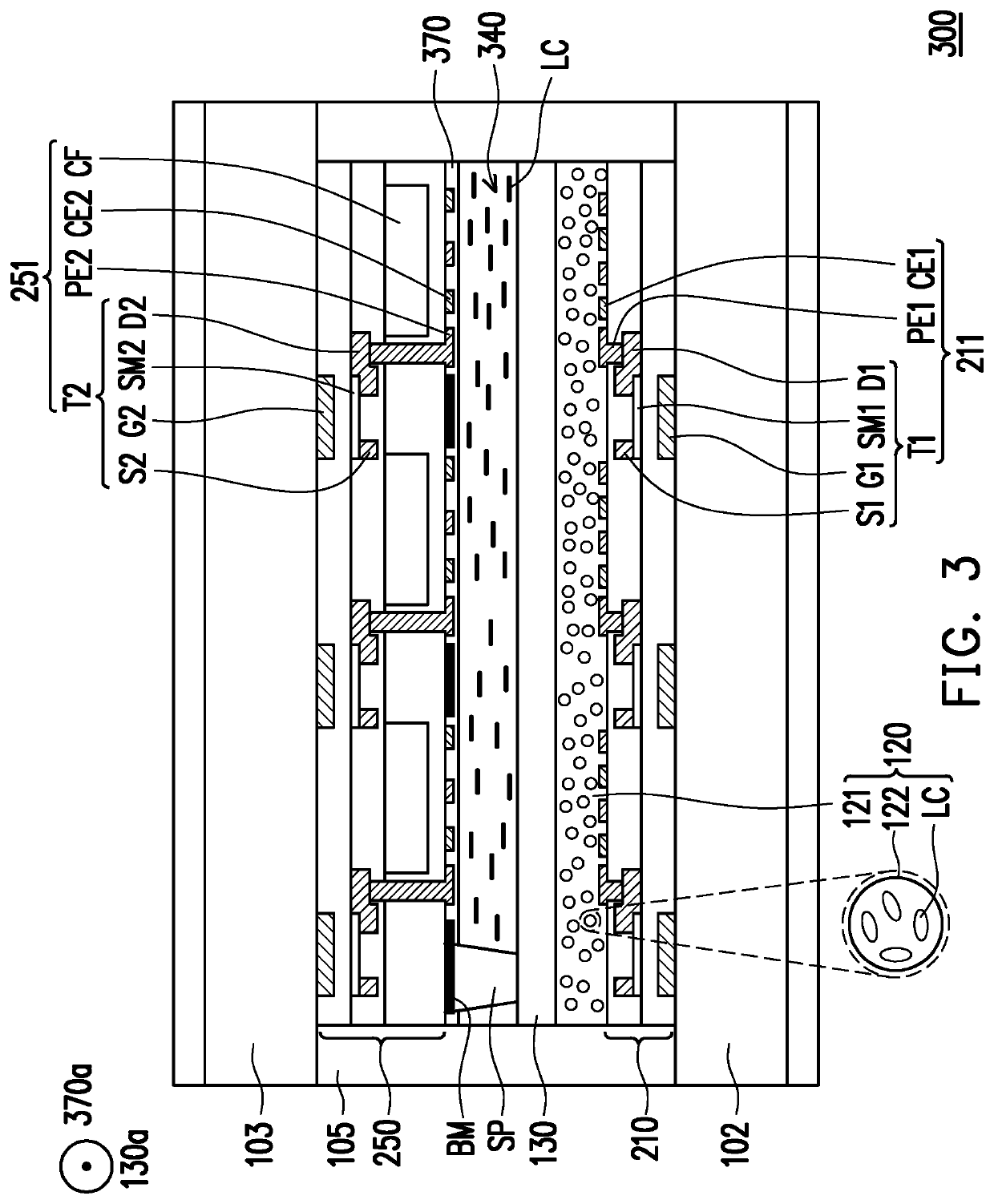
[0017]FIG. 1 is a cross section of a display panel according to the first embodiment of the invention. A display panel 100 can include a first polarizer 101, a first substrate 102, a first driving layer 110, a first display medium layer 120, a polarizing layer 130, a second display medium layer 140, a second driving layer 150, a second substrate 103, a second polarizer 104, and a sealant 105. The first substrate 102 and the second substrate 103 can be attached together by facing each other vertically via the sealant 105. The material of the first substrate 102 and the second substrate 103 can be glass, quartz, organic polymer, metal, or other suitable materials and have a certain thickness and support to construct the volume and contour of the display panel 100, but the invention is not limited thereto. The material of the sealant 105 is, for instance, an adhesive material that can attach the first substrate 102 and the second substrate 103 together. The first polarizer 101 is dispo...


PUM

PropertyMeasurementUnit
sizeaaaaaaaaaa
sizeaaaaaaaaaa
thicknessaaaaaaaaaa

Abstract

A display panel including a first substrate, a second substrate, a first display medium layer, a polarizing layer, and a second display medium layer is provided. The first display medium layer is disposed between the first substrate and the second substrate. The first display medium layer includes a first base material and a plurality of first encapsulated particles immobilized in the first base material. The average size of the first encapsulated particles is 1 nm to 400 nm. The polarizing layer is disposed between the first display medium layer and the second substrate. The polarizing layer is in contact with the first display medium layer. The second display medium layer is disposed between the polarizing layer and the second substrate.

Description

CROSS-REFERENCE TO RELATED APPLICATION[0001]This application claims the priority benefit of Taiwan application serial no. 106134620, filed on Oct. 6, 2017. The entirety of the above-mentioned patent application is hereby incorporated by reference herein and made a part of this specification.BACKGROUND OF THE INVENTIONField of the Invention[0002]The invention relates to an electronic apparatus, and more particularly, to a display panel.Description of Related Art[0003]To achieve the desired display effect, a technical design includes stacking two liquid crystal display panels, wherein one of the liquid crystal display panels is used as a display panel to control display grayscale and the other one is used as a shutter panel to control the passing of display light. This design can increase display contrast and alleviate color shift. However, stacking two display panels often produces an issue in alignment accuracy, and interference fringes are generated due to Moiré effect as a result,...

Claims


Application Information

Patent Timeline
Patent Type & Authority Patents(United States)
IPC IPC(8): G02F1/1335G02F1/1347G02F1/1334G02F1/133G02F1/1339G02F1/1343G02F1/1337
CPCG02F1/1334G02F1/13471G02F1/133528G02F1/1337G02F1/134363G02F2001/134372G02F1/1339G02F2201/123G02F1/133514G02F2201/121G02F1/13306G02F1/1347G02F1/133531G02F1/134372
Inventor CHEN, JU-CHINLEE, SEOK-LYULYANG, SYUAN-LINGWU, YANG-EN
Owner AU OPTRONICS CORP
Learn More