Optical tracking system and tracking method using the same
a tracking system and optical technology, applied in the field of optical tracking system and tracking method, can solve the problems of difficult to calculate the exact diameter of the circle of the marker, and achieve the effect of expanding an available area, reducing accuracy, and not affecting the accuracy of the position of the marker uni
- Summary
- Abstract
- Description
- Claims
- Application Information
AI Technical Summary
Benefits of technology
Problems solved by technology
Method used
Image
Examples
first embodiment
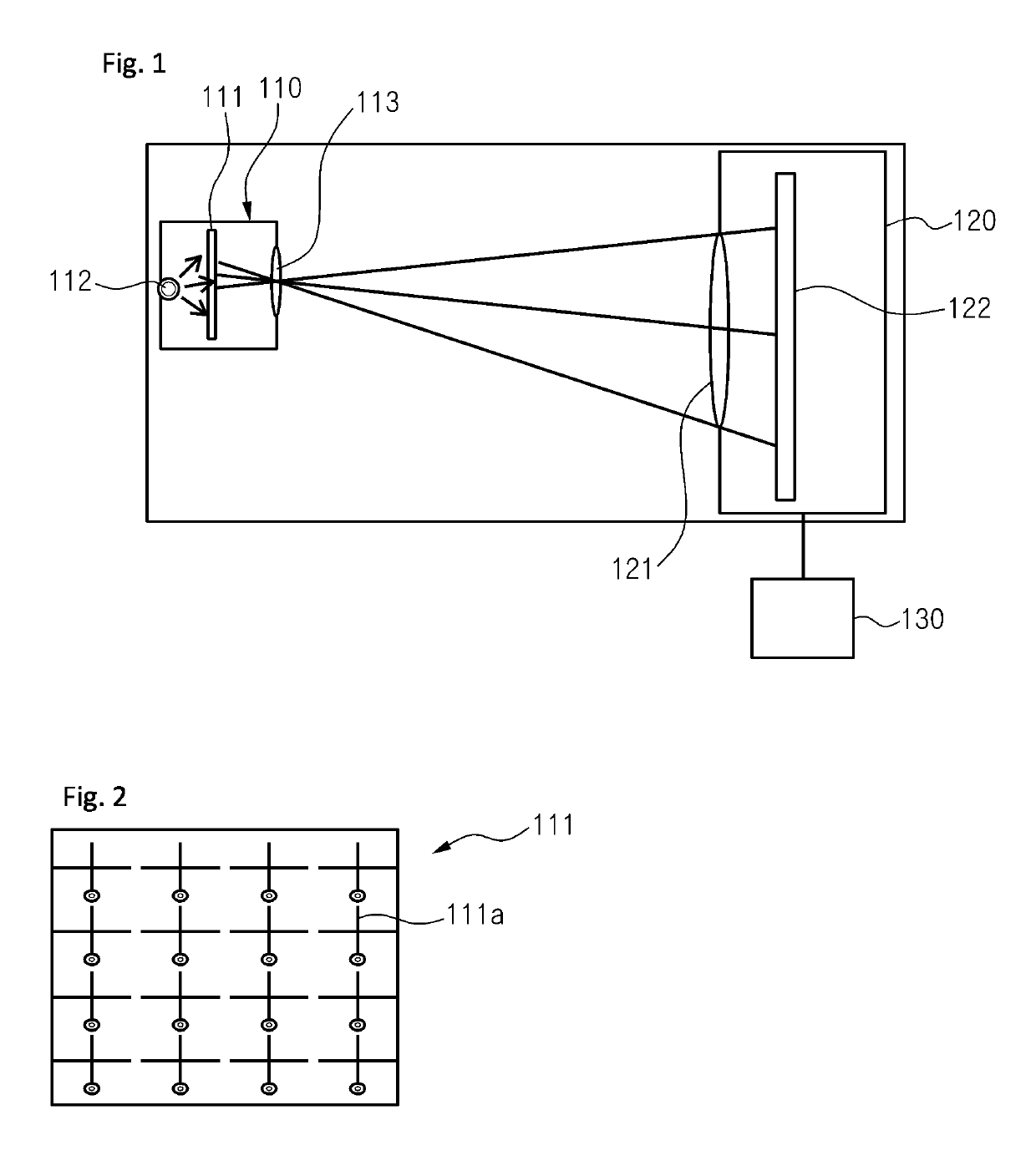
[0082]FIG. 1 is a schematic diagram of a tracking system according to a first embodiment of the present invention, and FIG. 2 is an example drawing of a pattern portion of a marker unit.
[0083]Referring to FIGS. 1-2, a tracking system according to a first embodiment of the present invention includes a marker unit 110, an image forming unit 120, and a processor 130.
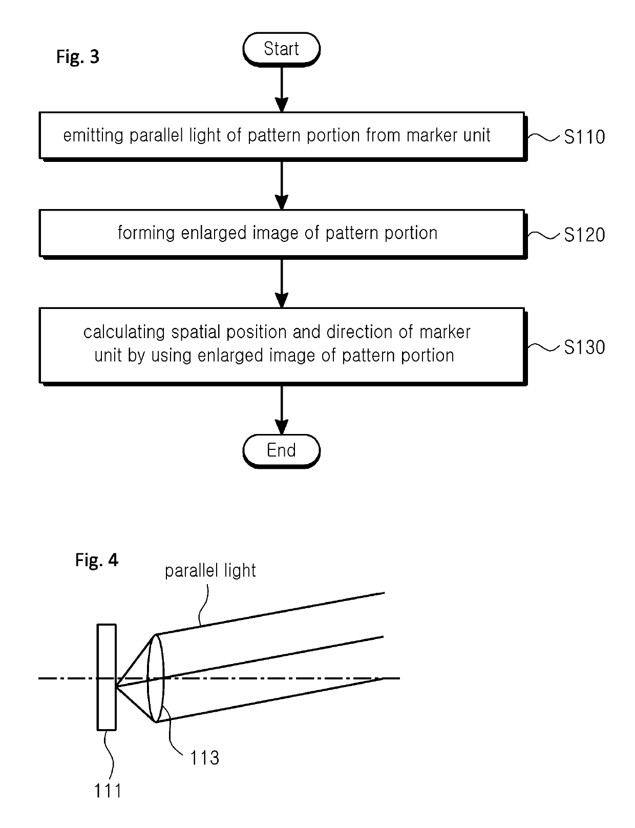
[0084]The marker unit 110 attached on a target and emits a parallel light to form an enlarged image of a pattern portion 111 which is included inside the marker unit 110.
[0085]For example, the marker unit 110 may include a pattern portion 111, a light source 112, and a first lens portion 113.
[0086]The pattern portion is formed by plurality of pattern portions 111a in a regular shape with an interval. For example, the pattern portion 111 may be formed to pass light except for an area in which pattern portions 111a are formed. Alternatively, the pattern portions 111a may be formed to pass light an area in which the pattern po...
second embodiment
[0118]An optical tracking system according to an embodiment of the present invention is substantially the same as the optical tracking system of the first embodiment except for arranging two image forming units, a detailed explanation of other elements except for an arrangement of the image forming unit is omitted.
[0119]FIG. 11 is a schematic diagram of a tracking system according to a second embodiment of the present invention.
[0120]Referring to FIG. 11, an optical tracking system according to an embodiment of the present invention includes a maker unit 210, first and second image forming units 220a and 220b, and a processor 230.
[0121]The first and second image forming units 220a and 220b are arranged at an interval with the marker unit 210 as the center to receive a parallel light of the pattern portion 211 emitted from the marker unit 210 and form enlarged images of a pattern portion 211 which are different to each other. Herein, it may be preferable to arrange the first and seco...
third embodiment
[0137]An optical tracking system according to an embodiment of the present invention is substantially the same as the optical tracking system of the first embodiment except for some elements, detailed explanations of other elements except for a marker unit is omitted.
[0138]FIG. 13 is a schematic diagram of an optical tracking system according to a third embodiment of the present invention.
[0139]Referring to FIG. 13, an optical tracking system according to an embodiment of the present invention includes one marker unit 310, a first image forming unit 320, and a processor 330.
[0140]The marker unit 310 may include a pattern portion 311, first and second light sources 312a and 312b, and first and second lens portions 313a and 313b.
[0141]The pattern portion 311 is formed by plurality of pattern portions (not shown) with an interval. Herein, two pattern portions 311 may be formed which are corresponding to the first and second lens portions 313a and 313b as shown in FIG. 13, or, as well ...
PUM
 Abstract
Description
Claims
Application Information
 - R&D
- Intellectual Property
- Life Sciences
- Materials
- Tech Scout
- Unparalleled Data Quality
- Higher Quality Content
- 60% Fewer Hallucinations
Browse by: Latest US Patents, China's latest patents, Technical Efficacy Thesaurus, Application Domain, Technology Topic, Popular Technical Reports.
© 2025 PatSnap. All rights reserved.Legal|Privacy policy|Modern Slavery Act Transparency Statement|Sitemap|About US| Contact US: help@patsnap.com


