Repeatedly pressure operated ported sub with multiple ball catcher

a technology of ported subs and ball catcher, which is applied in the direction of sealing/packing, borehole/well accessories, construction, etc., can solve the problems of impracticality of devices for space and cost reasons

Active Publication Date: 2019-06-04
BAKER HUGHES INC
View PDF31 Cites 0 Cited by
  • Summary
  • Abstract
  • Description
  • Claims
  • Application Information

AI Technical Summary

Problems solved by technology

The limitation of this device is that it can handle only one ball so if there are multiple balls involved, then multiple ball catchers each having a seat to accept a different sized ball is needed.
In fracturing applications, there can be as many as dozens of balls blown through seats that need to be captured, making this device impractical for space and cost reasons.

Method used


Image

  • Repeatedly pressure operated ported sub with multiple ball catcher
  • Repeatedly pressure operated ported sub with multiple ball catcher
  • Repeatedly pressure operated ported sub with multiple ball catcher

Examples


Embodiment Construction

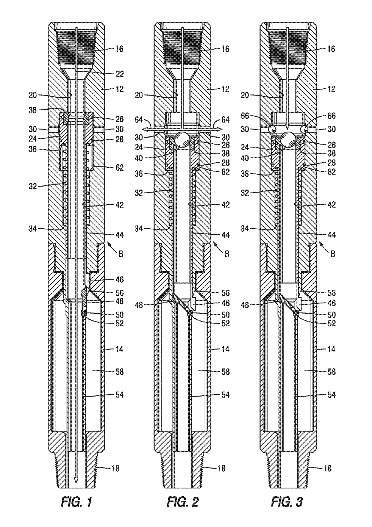
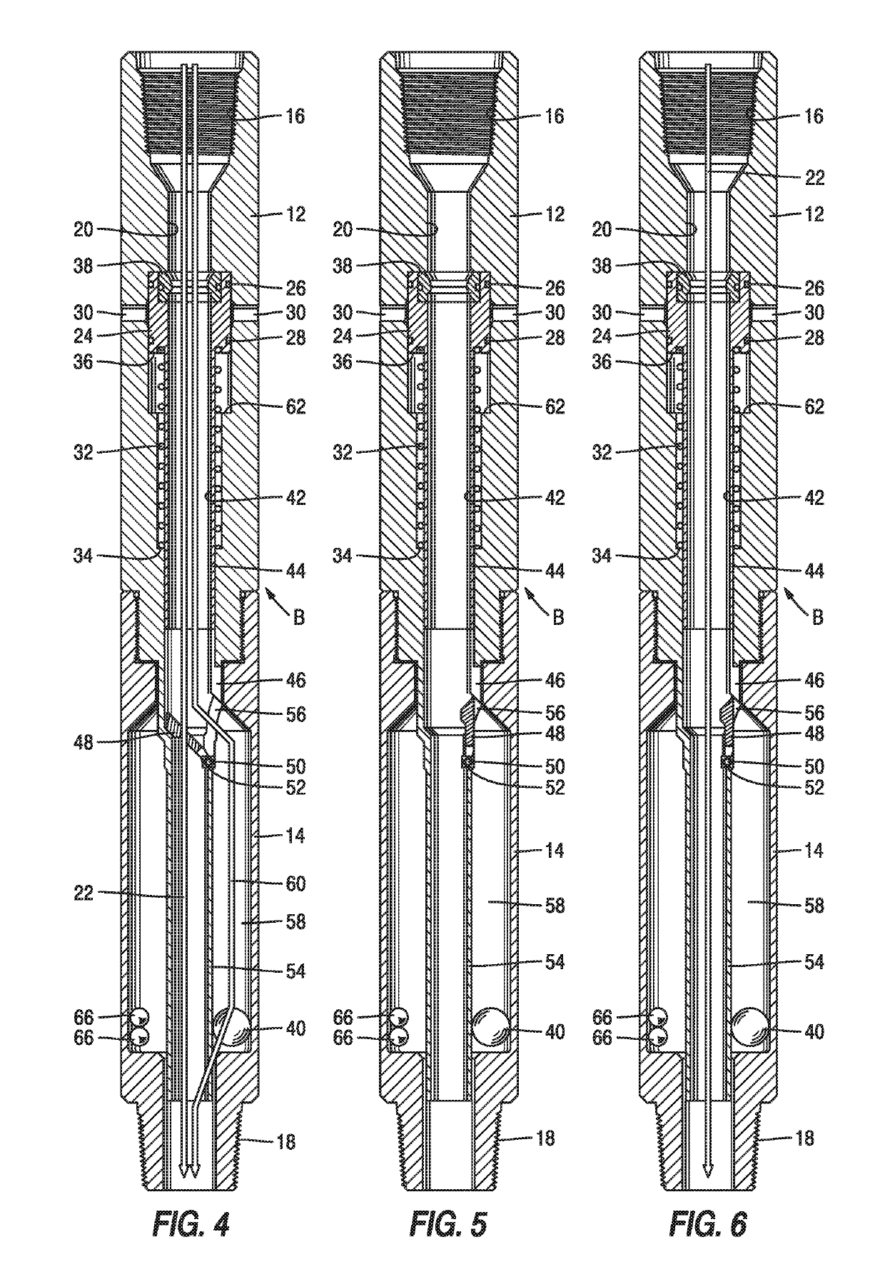
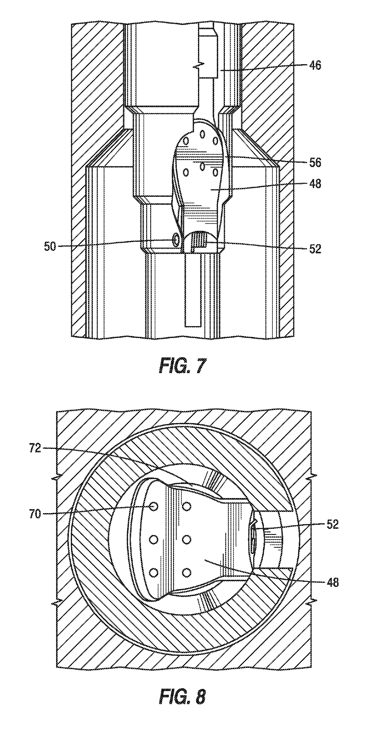
[0014]Referring to FIG. 1, the ball catcher B has an upper housing 12 connected to a lower housing 14. A drill string that is not shown is connected above to connection 16 and below to connection 18. A through passage 20 extends through housing components 12 and 14. Arrow 22 shows flow through the ball catcher B in the run in position. A piston 24 has spaced seals 26 and 28 that straddle lateral ports 30 allowing piston 24 to act as a valve member for ports 30. A spring 32 pushes off a shoulder 34 in upper housing 12 to put an uphole force on surface 36 of piston 24. A ball seat 38 is supported by piston 24 such that without a seated ball 40 on seat 38 the through passage 20 is open between connections 18 and 16. Connected to piston 24 is an extension tube 42 that ends at a lower end 44. Continuing below the lower end 44 is an extending segment 46 that is disposed radially outside of a diverter or flapper 48 that pivots above a pin 50 that has a torsion spring 52 about pin 50 that b...


PUM


Abstract

A ball seat is integrated with a movable biased sleeve. Sleeve movement against its bias moves a diverter from a position outside the through passage to a position across the main passage such that any balls that drop down will be directed by the diverter into an annular retention volume. In treatment of the formation for fluid loss the movement of a seat with the seated ball opens lateral ports for delivery of sealing material and moves the diverter. Smaller balls are then introduced to close lateral ports above the seated ball so pressure can be built to shift the sleeve and extrude the first ball. Once the seated ball blows through, the smaller balls come through the seat and are all diverted to an annular capture volume. The device is resettable for multiple operations. Fluid flow cessation closes lateral ports and opens a through passage retracting the diverter.

Description

FIELD OF THE INVENTION[0001]The field of the invention is ported subs capable of multiple cycles in conjunction with downhole ball catchers and more particularly where different sized balls can be diverted to an annular catch volume around a through passage with a diverter in one position and the through passage can be unobstructed with the diverter in a second position.BACKGROUND OF THE INVENTION[0002]Ball catchers are known in the art as described in U.S. Pat. No. 7,735,548 and US 2010 / 0236782. Their purpose is to stop balls blown through ball seats above from going further downhole and preventing operation of equipment further downhole, flow, or the ability to introduce other tools further downhole. One way to accomplish at least some of these objectives is to be able to store the captured balls in a volume outside the main passage. One device that captures a single ball outside a main passage is shown in U.S. Pat. No. 6,920,930, where the ball seat has a swing-away feature with ...

Claims


Application Information

Patent Timeline
Patent Type & Authority Patents(United States)
IPC IPC(8): E21B34/14E21B23/00E21B21/10E21B34/00
CPCE21B34/14E21B21/103E21B23/006E21B23/004E21B2034/007E21B2200/06E21B34/142
Inventor HERED, WILLIAM A.
Owner BAKER HUGHES INC
Why Eureka
Try Eureka